
Method and apparatus for measuring parameters of a stratified flow

a stratified flow and measurement method technology, applied in the direction of liquid/fluent solid measurement, volume/mass flow by differential pressure, instruments, etc., can solve the problems of high pipe wear, high process downtime costs, and high energy consumption

Inactive Publication Date: 2005-11-03
CIDRA
View PDF67 Cites 58 Cited by
  • Summary
  • Abstract
  • Description
  • Claims
  • Application Information

AI Technical Summary

Benefits of technology

[0020] The foregoing and other objects, and features of the present invention will become...

Problems solved by technology

If the level of stratification extends to the point where deposition velocity is reached, the solids begin to settle to the bottom of the pipe, and if the condition is undetected and persists, complete blockage of the pipe can occur, resulting in high costs associated with process downtime, clearing of the blockage, and repair of damaged equipment.
However, this technique has two significant drawbacks due to operating at higher velocities: it causes higher energy usage due to higher friction losses, and it causes higher pipe wear due to abrasion between the solids and the pipe inner surface.
This technique may also be undesirable to due high water consumption.
While existing technologies may be well-suited for aggressive, large diameter flows, these technologies may be unsuitable for stratified flows, which can adversely affect accuracy in measuring physical parameters of the flow.
This technique was deemed to be not very successful due to poor repeatablility and other problems.
While this technique is promising, it is an invasive technique requiring the thermal probes to be placed in the pipe.
Such invasive techniques have drawbacks in that they require the process to be stopped to allow for installation and maintenance of the probes.

Method used


Image

  • Method and apparatus for measuring parameters of a stratified flow
  • Method and apparatus for measuring parameters of a stratified flow
  • Method and apparatus for measuring parameters of a stratified flow

Examples


Embodiment Construction

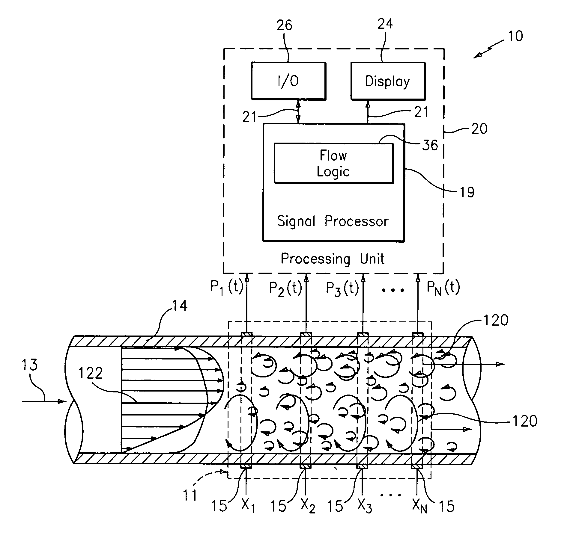
[0043] As described in commonly-owned U.S. Pat. No. 6,609,069 to Gysling, entitled “Method and Apparatus for Determining the Flow Velocity Within a Pipe”, and U.S. patent application Ser. No. 10 / 007,736, filed on Nov. 11, 2001, which are incorporated herein by reference in their entirety, unsteady pressures along a pipe caused by coherent structures (e.g., turbulent eddies and vortical disturbances) that convect with a fluid flowing in the pipe, contain useful information regarding parameters of the fluid. The present invention provides various means for using this information to measure parameters of a stratified flow, such as, for example, velocity, level / degree of stratification, and volumetric flow rate.

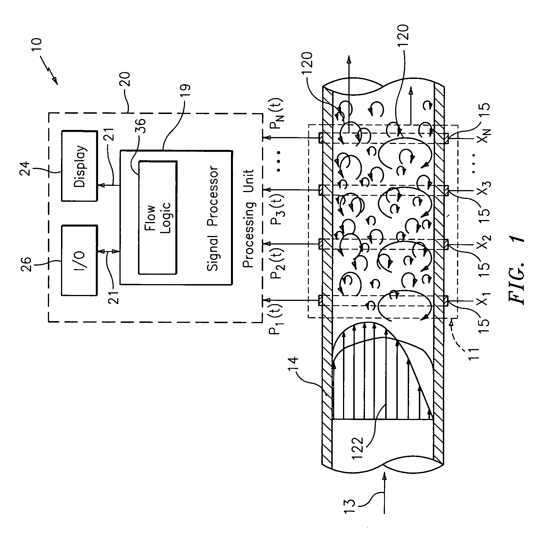
[0044] Referring to FIG. 1, an apparatus 10 for measuring at least one parameter associated with a flow 13 flowing within a duct, conduit or other form of pipe 14, is shown. The parameter of the flow 13 may include, for example, at least one of: velocity of the flow 13, volumetr...


PUM


Abstract

Various methods are described for measuring parameters of a stratified flow using at least one spatial array of sensors disposed at different axial locations along the pipe. Each of the sensors provides a signal indicative of unsteady pressure created by coherent structures convecting with the flow. In one aspect, a signal processor determines, from the signals, convection velocities of coherent structures having different length scales. The signal processor then compares the convection velocities to determine a level of stratification of the flow. The level of stratification may be used as part of a calibration procedure to determine the volumetric flow rate of the flow. In another aspect, the level of stratification of the flow is determined by comparing locally measured velocities at the top and bottom of the pipe. The ratio of the velocities near the top and bottom of the pipe correlates to the level of stratification of the flow. Additional sensor arrays may provide a velocity profile for the flow. In another aspect, each of the sensors in the array includes a pair of sensor half-portions disposed on opposing lateral surfaces of the pipe, and the signal processor determines a nominal velocity of the flow within the pipe using the signals.

Description

CROSS-REFERENCE TO RELATED PATENT APPLICATIONS [0001] The present application claims the benefit of U.S. Provisional Patent Application No. 60 / 522,164, (CiDRA Docket No. CC-0732) filed Mar. 10, 2004, which is incorporated by reference herein in its entirety.TECHNICAL FIELD [0002] This invention relates to a method and apparatus for measuring parameters such as velocity, level of stratification, and volumetric flow rate of a stratified flow within a pipe. BACKGROUND [0003] Many industrial fluid flow processes involve the transportation of a high mass fraction of high density, solid materials through a pipe. For example, a process known as hydrotransport is used in many industries to move solids from one point to another. In this process, water is added to the solids and the resulting mixture is pumped through typically large diameter pipes. [0004] Operation of a hydrotransport line typically involves some degree of stratification, where flow velocity near the bottom of the pipe is le...

Claims


Application Information

Patent Timeline
IPC IPC(8): G01F1/34G01F1/704G01F1/7082G01F1/712G01F1/74
CPCG01F1/34G01F1/666G01F1/74G01F1/7082G01F1/712G01F1/704
Inventor GYSLING, DANIEL L.FERNALD, MARK R.BAILEY, TIMOTHY J.VIEGA, JOHN
Owner CIDRA
Learn More