Apparatus for tightening threaded member

a technology for threaded members and actuators, which is applied in the direction of power driven tools, metal-working apparatus, wrenches, etc., can solve the problems of manual operation of temporary tightening operation with tiresome and troublesome, requiring certain time and burden, and affecting the engine's productivity, etc., and achieves smooth loosening

Inactive Publication Date: 2005-11-10
HONDA MOTOR CO LTD
View PDF4 Cites 24 Cited by
  • Summary
  • Abstract
  • Description
  • Claims
  • Application Information

AI Technical Summary

Benefits of technology

[0030] The rotational part can be rotated in either of two directions. When rotating in the one direction, the threaded member is tightened. When rotating in the other, the threaded member is loosened. The use of the apparatus is advantageous in that the threaded member does not seize up in or on the companion threaded member and hence the threaded member can be smoothly loosened out of the companion threaded member.

Problems solved by technology

For the aforementioned method, however, the operator manually performs the temporary tightening operation with tiresomeness and troublesomeness.
Moreover, the final tightening operation subsequent to such problematic temporary tightening operation requires certain time and burden.
The method involving these two operations are less suitable for improving productivity of the engine.

Method used


Image

  • Apparatus for tightening threaded member
  • Apparatus for tightening threaded member
  • Apparatus for tightening threaded member

Examples


first embodiment

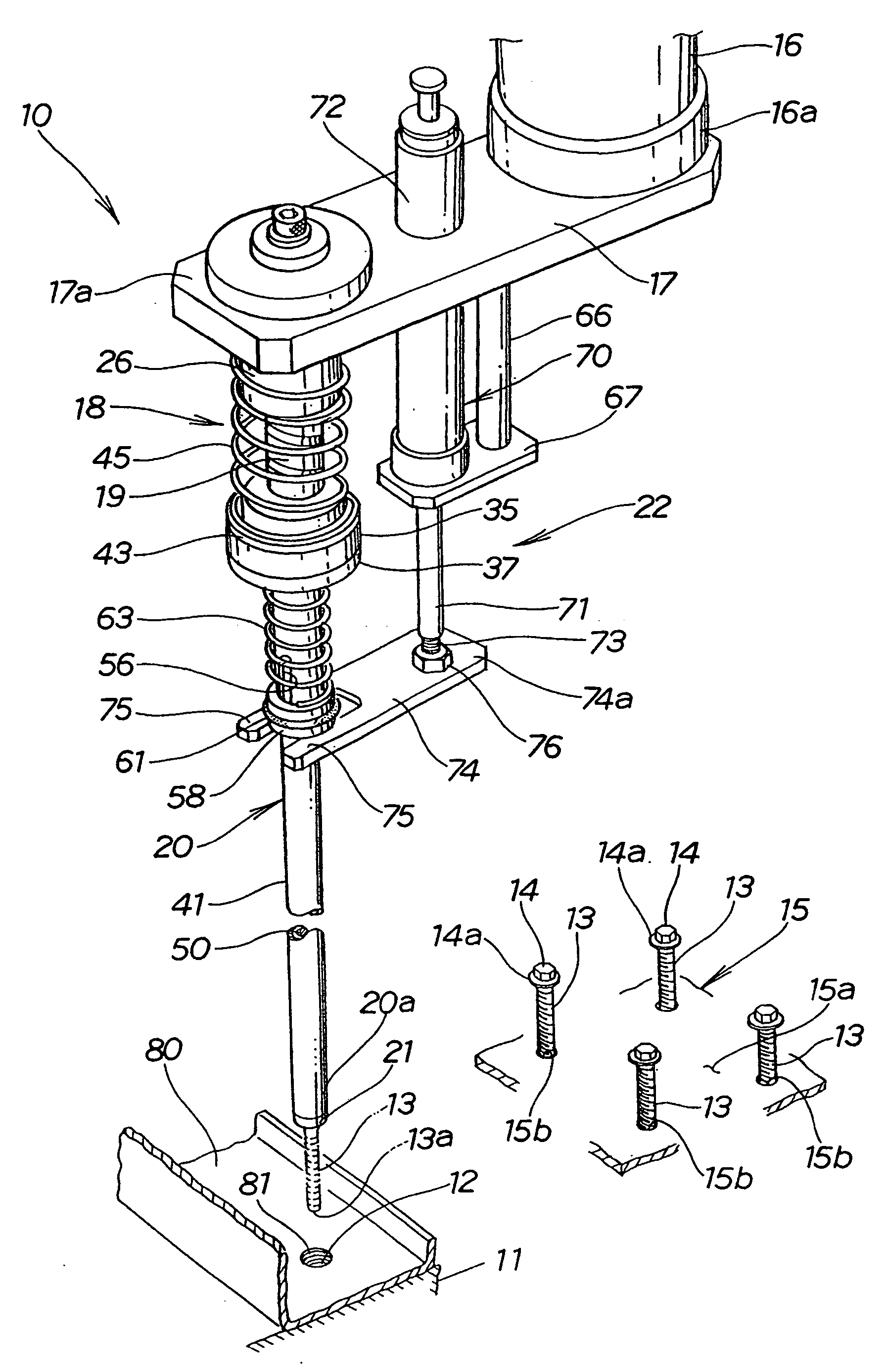
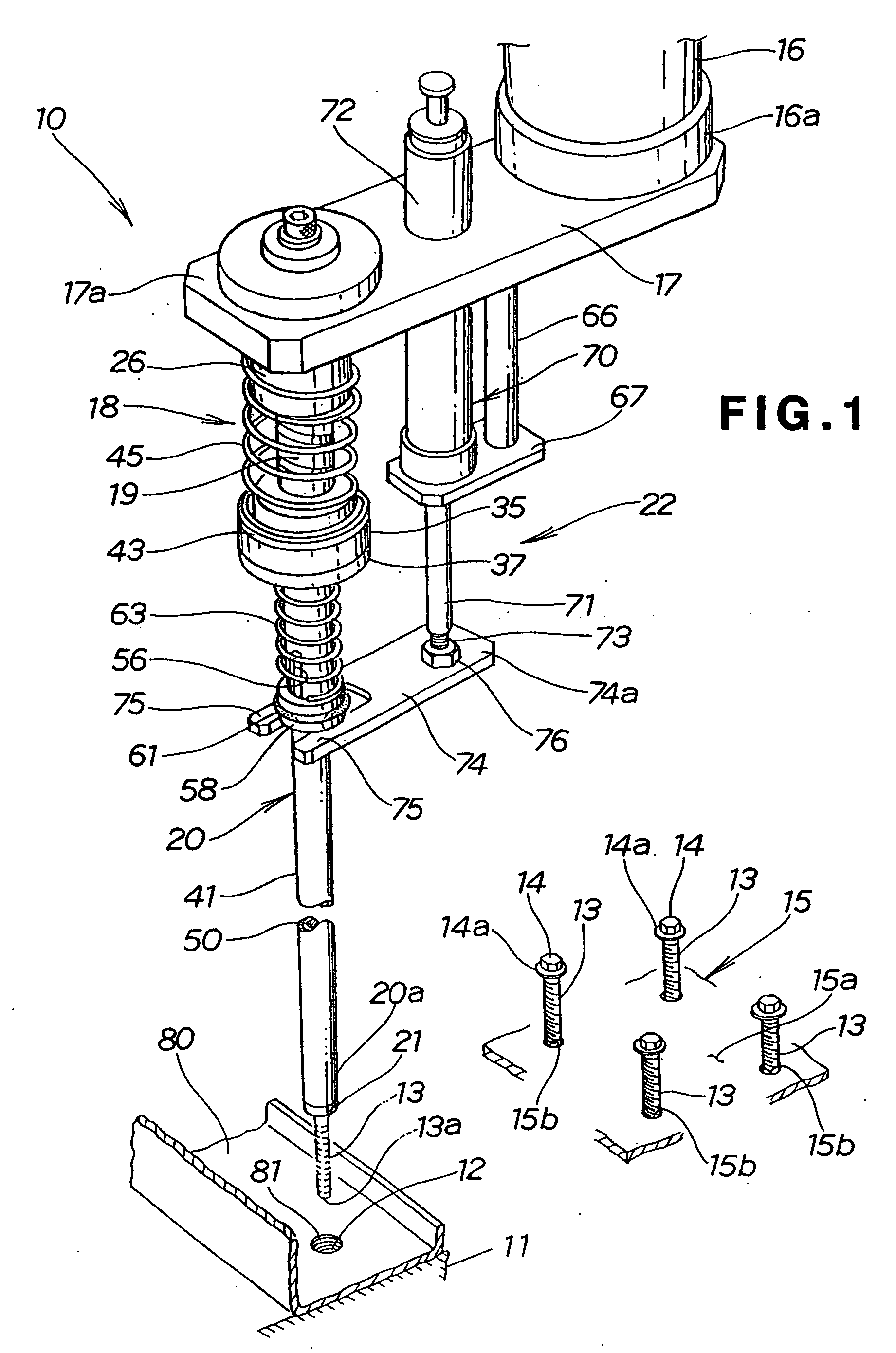
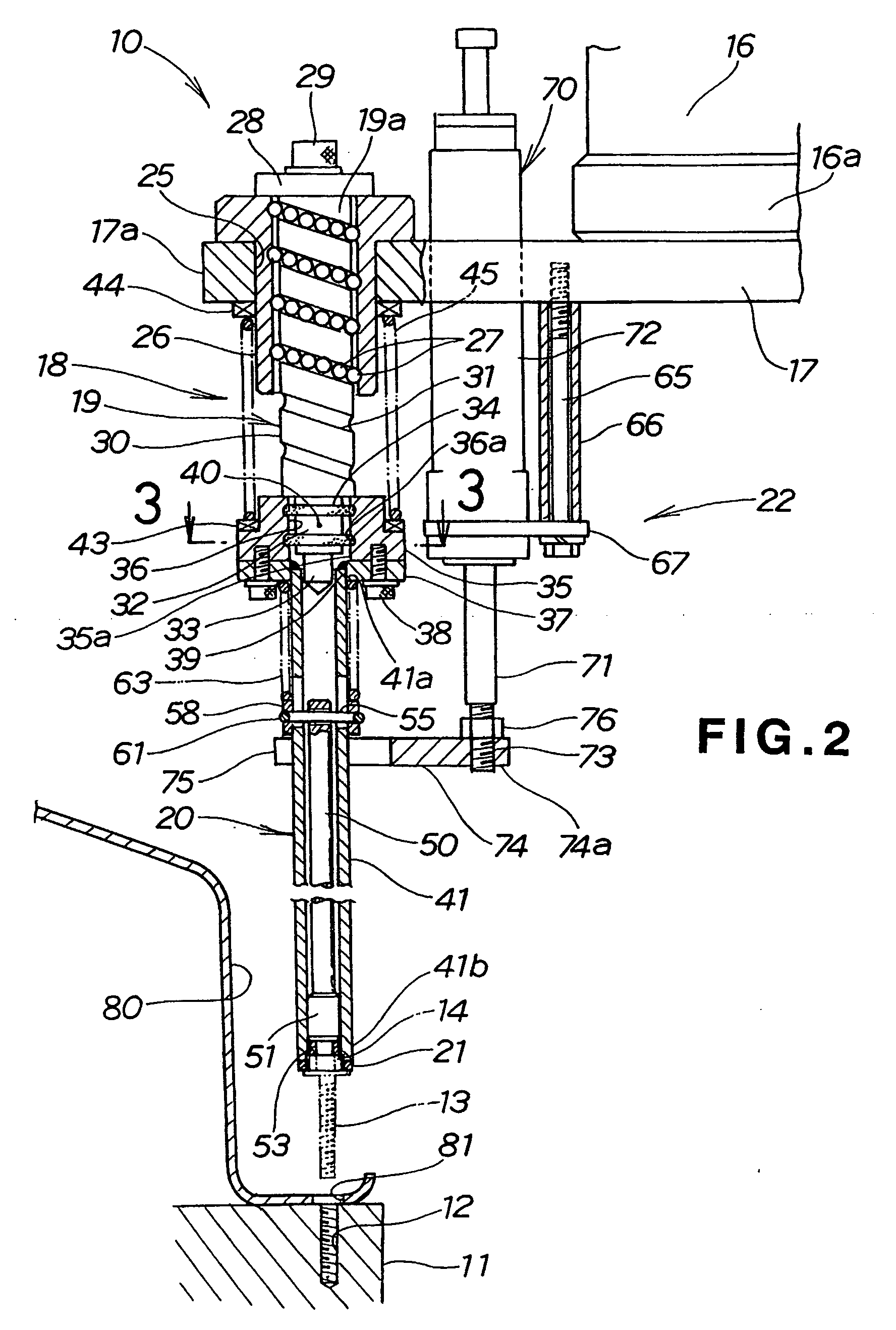
[0056] Referring to FIG. 1, there is shown an apparatus 10 for tightening a threaded member according to the present invention. In the illustrated embodiment, the threaded member is a hexagon head bolt 13. The apparatus 10 includes a screwing mechanism 18 having a rotational shaft 19, and an automatic robot arm 16 (axially moving means for moving axially to rotate the rotational shaft 19). The screwing mechanism 18 is mounted via a bracket 17 to a lower end 16a of the arm 16. The apparatus 10 further includes a shaft member 20 pivotably connected to a lower end of the rotational shaft 19 of the screwing mechanism 18. The robot arm 16 is arranged to move axially of the rotational shaft 19 so as to rotate the shaft 19. That is, the axial movement of the arm 16 is converted to rotation of the rotational shaft 19. The shaft member 20 has a socket portion 21 provided at a distal end thereof. The socket portion 21 is designed or sized to receive a head 14 of the bolt 13 therein. As will b...

second embodiment

[0153] In the second embodiment, the inner periphery 147a is formed to provide the hexagonal cross-section, but may be of circular, octagonal or other polygonal cross-section to serve the same function as discussed above.

[0154] Referring to FIG. 17, the lower cylinder member 137 includes a cylinder body 148. The cylinder body 148 has its inner periphery 148a formed to provide a hexagonal cross-section.

[0155] The slider 140 is a pipe of hexagonal cross-section and is telescoped or inserted into the cylinder body 148.

[0156] The cylinder body 148 has mounting apertures 148b, 148b formed to laterally extend therethrough. The slider 140 has mounting apertures 140d, 140d formed to laterally extend therethrough. The mounting bolt 141 is inserted through the apertures 148b, 148b, 140d, 140d.

[0157] The mounting bolt 141 has a nut 152 tightened thereonto to mount the slider 140 to the cylinder body 148.

[0158] Providing the inner periphery 148a and the slider 140 with the hexagonal configu...


PUM


Abstract

An apparatus (10) for tightening a hexagon head bolt (13) includes a vertically movable automatic robot arm (16), a screwing mechanism (18) having a rotational part (19), a shaft member (20) mounted to the rotational part, a socket portion (21) mounted to the shaft member for receiving therein a head (14) of the bolt, and a retention means (22) for retaining the head received in the socket portion or retaining the head released from the socket portion. When the arm moves vertically with the head received in the socket portion, the rotational part is rotated along with the shaft member and the socket portion to screw the bolt into a threaded aperture (12) of a crankcase (11) of an engine.

Description

TECHNICAL FIELD [0001] The present invention relates to an apparatus for tightening threaded members such as bolts or nuts for coupling components to workpieces. BACKGROUND ART [0002] Known bolt-tightening apparatus (so called “nut runner”) for tightening bolts include electric motors and tightening members for tightening bolts. The tightening members have receiving portions for receiving heads of the bolts. With the heads of the bolts received within the receiving portions, the electric motors are driven to rotate the tightening members, so as to tighten the bolts. [0003] One example of such apparatuses is shown in, for example, Japanese Patent Laid-Open Publication No. HEI 6-31644. [0004] The apparatus as disclosed in the publication includes an electric nut runner and a bolt-feeding device for feeding bolts to the nut runner. The nut runner is driven by an electric motor to tighten the bolt. [0005]FIG. 23 hereof shows an exemplary conventional method of screwing bolts 202 for att...

Claims


Application Information

Patent Timeline
Patent Type & Authority Applications(United States)
IPC IPC(8): B23P19/06B25B21/00B25B23/12
CPCB23P19/06B25B15/06B25B23/12
Inventor SASAKI, SHUITI
Owner HONDA MOTOR CO LTD
Why Eureka
Try Eureka