Power tool with a rotating and/or hammering drive mechanism

Inactive Publication Date: 2005-11-10
ROBERT BOSCH GMBH
View PDF15 Cites 20 Cited by
  • Summary
  • Abstract
  • Description
  • Claims
  • Application Information

AI Technical Summary

Benefits of technology

[0003] The hand-operated power tool of the invention has the advantage over the prior art of simple disposition, low cost an

Problems solved by technology

In hand-operated power tools of this kind, vibrations occur upon use, particularly in the hammering mode, th

Method used


Image

  • Power tool with a rotating and/or hammering drive mechanism
  • Power tool with a rotating and/or hammering drive mechanism
  • Power tool with a rotating and/or hammering drive mechanism

Examples


Embodiment Construction

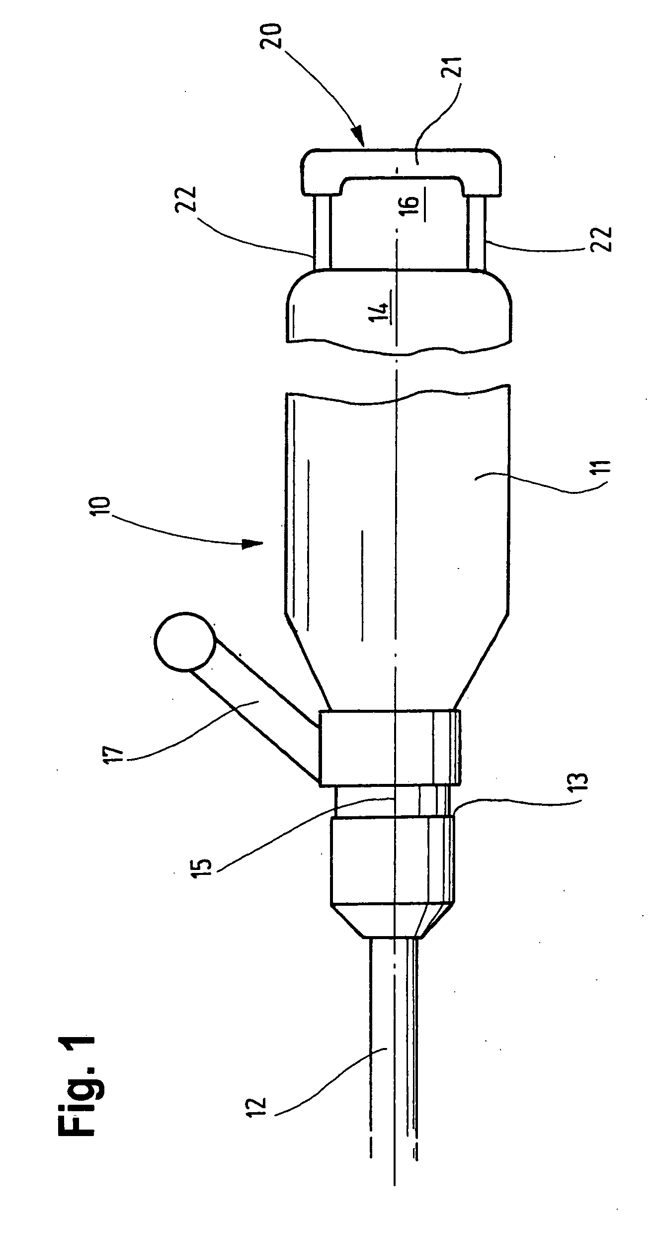
[0010] In FIG. 1, a hand-operated power tool 10, particularly in the form of a drill hammer and / or jackhammer, for example, is shown schematically. This may be a jackhammer (pavement-breaking hammer), with a weight of 14 kg or more, for instance. Instead, it may be a drill hammer and / or jackhammer which alternatively makes drilling operation with hammering operation possible, or only drilling operation, or only hammering operation.

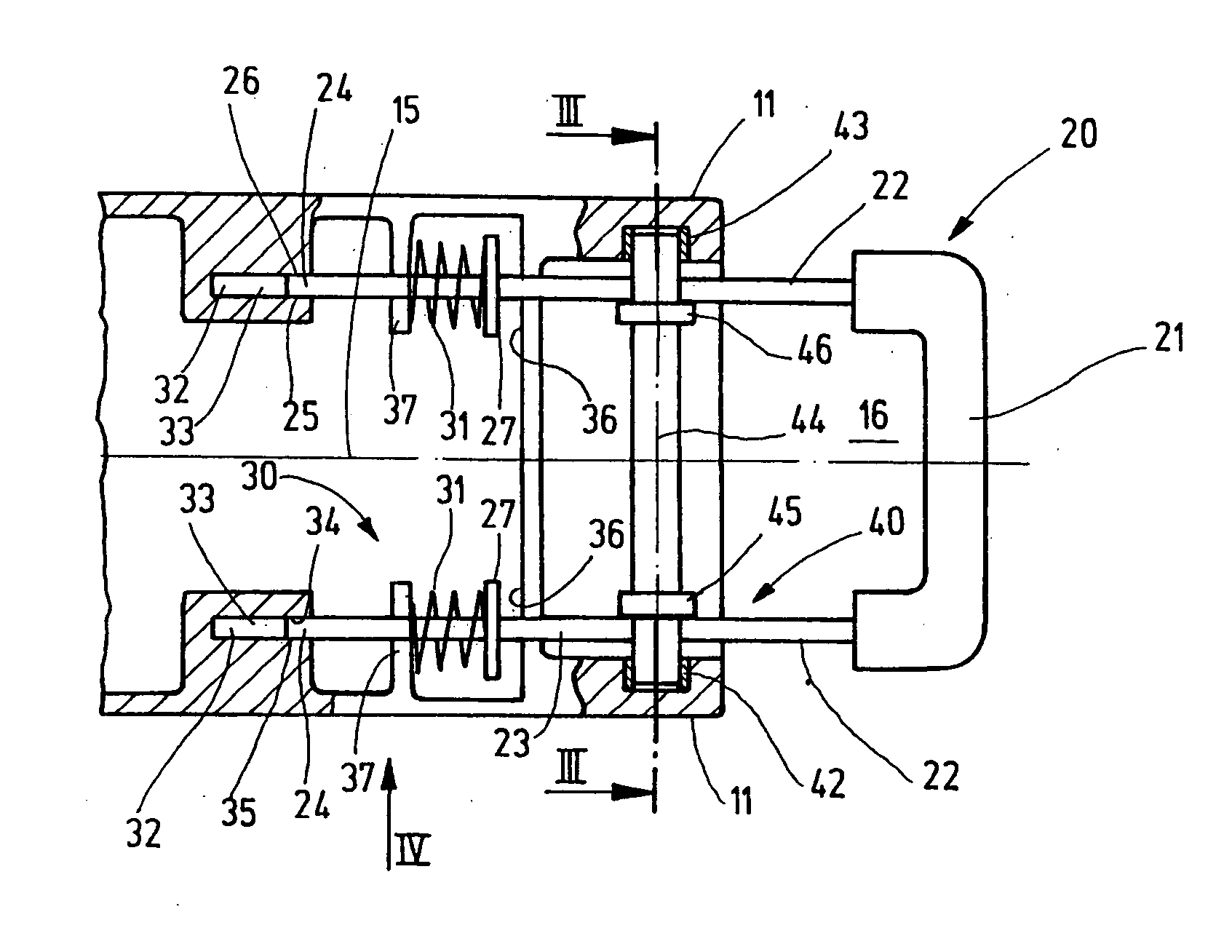
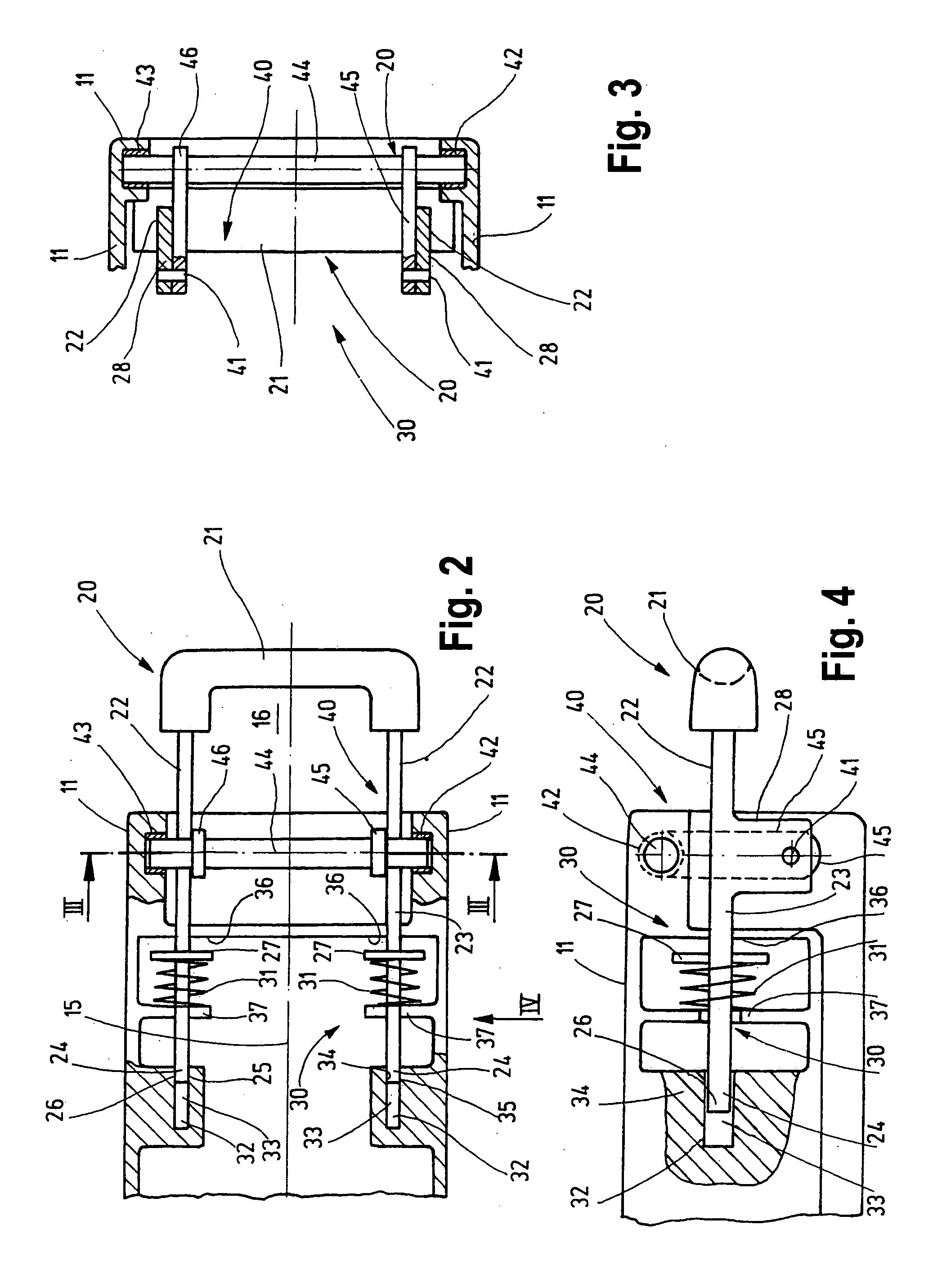
[0011] The hand-operated power tool 10 has a housing generally identified by reference numeral 11. In its interior, this housing contains a conventional drive mechanism, not further shown, such as an electric drive motor, which operates via a gear on a downstream drilling and / or hammering mechanism. The drive mechanism serves to drive a tool 12, represented only schematically, which is received interchangeably in the usual way in a tool receptacle 13. In the rear region 14, remote from the tool receptacle 13, there is a handle assembly 20, for grasping an...


PUM

PropertyMeasurementUnit
Widthaaaaaaaaaa
Depthaaaaaaaaaa

Abstract

A hand-operated power tool (10), in particular a drill hammer and/or jackhammer, has a housing (11) which has a drive mechanism for driving a tool (12) that is receivable in a tool receptacle (13) and, in the rear region (14), remote from the tool receptacle (13), has a handle assembly (20) for grasping and handling that engages the housing (11). The handle assembly (20) is vibration-damped with respect to the housing (11), with the components contained in it, at least and substantially in the axial direction, by means of a vibration-damping device (FIG. 1).

Description

BACKGROUND OF THE INVENTION [0001] The invention is based on a hand-operated power tool, in particular a drill hammer and / or jackhammer. [0002] In hand-operated power tools of this kind, vibrations occur upon use, particularly in the hammering mode, that make the work more difficult. Attempts have been made to reduce such vibration by means of such devices as complex systems of double-shell construction, or with parallel oscillators. Such systems are very expensive and make a large structural volume necessary. SUMMARY OF THE INVENTION [0003] The hand-operated power tool of the invention has the advantage over the prior art of simple disposition, low cost and a small structural volume, and at the same time it is not vulnerable to external mechanical impairments, dirt, or the like. [0004] By the provisions recited in the further claims, advantageous refinements of and improvements to the hand-operated power tool defined by claim 1 are possible. With the characteristics of claim 2, wit...

Claims


Application Information

Patent Timeline
IPC IPC(8): B25D17/04B25D17/24B25F5/02B25G1/01
CPCB25D17/043Y10T16/48Y10T16/44B25D17/04
Inventor HELLBACH, MANFREDMUELLER, FRANKMEIXNER, GERHARDSTEINKE, HUBERTLENNARTZ, JUERGEN
Owner ROBERT BOSCH GMBH
Why Eureka
Try Eureka