
Device for measuring the level of a fluid in a fuel tank of a motor vehicle

a technology for fuel tanks and liquids, applied in the direction of instruments, machines/engines, using reradiation, etc., can solve the problems of unfavorably great slopes of characteristic curves, and achieve the effect of simplifying the device and being especially economical

Inactive Publication Date: 2007-05-08
ROBERT BOSCH GMBH
View PDF10 Cites 12 Cited by
  • Summary
  • Abstract
  • Description
  • Claims
  • Application Information

AI Technical Summary

Benefits of technology

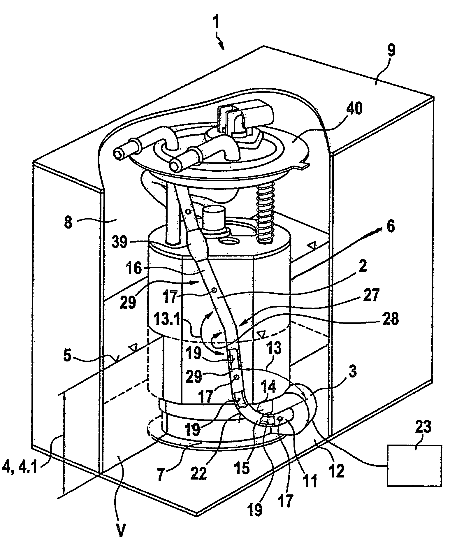
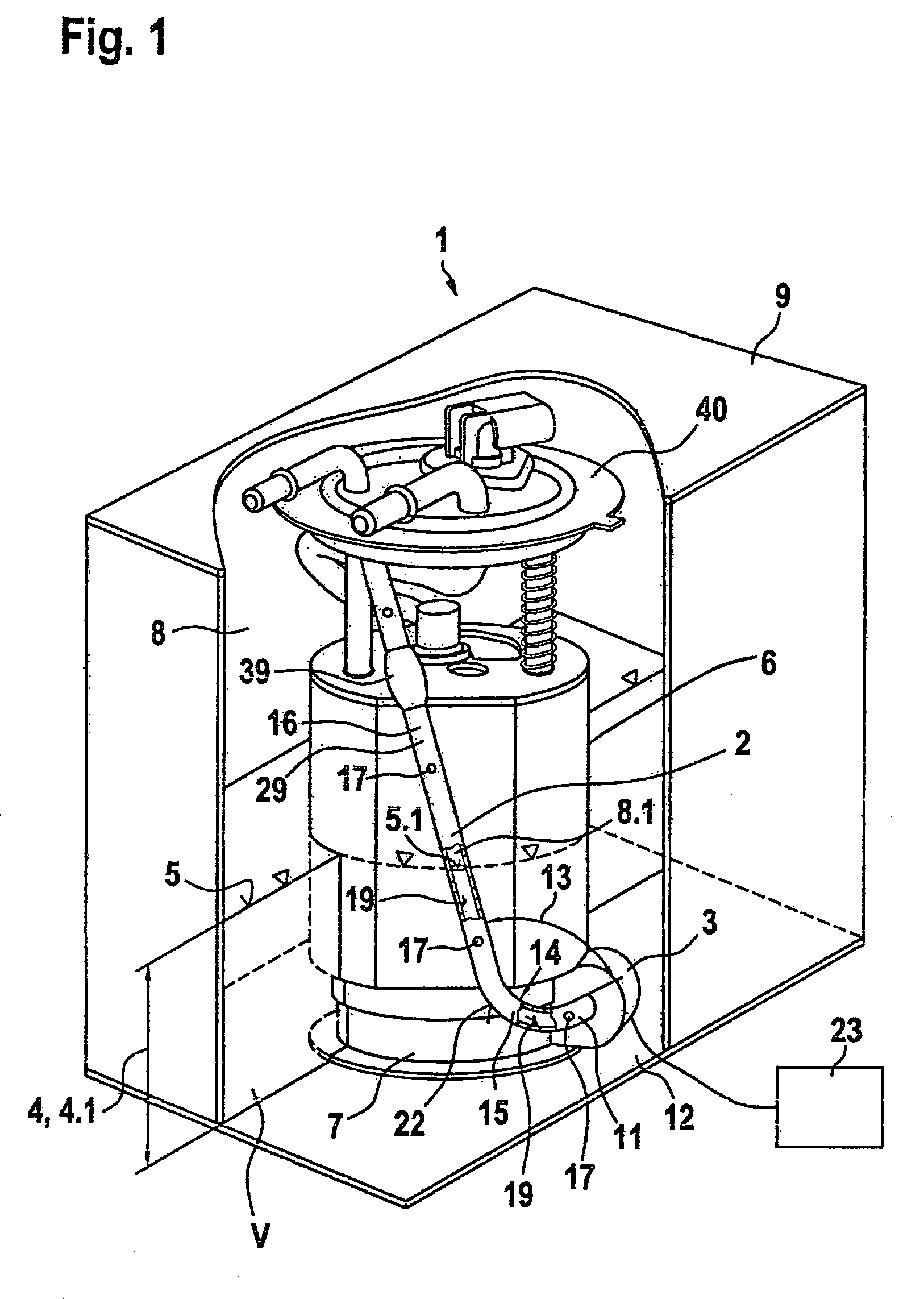
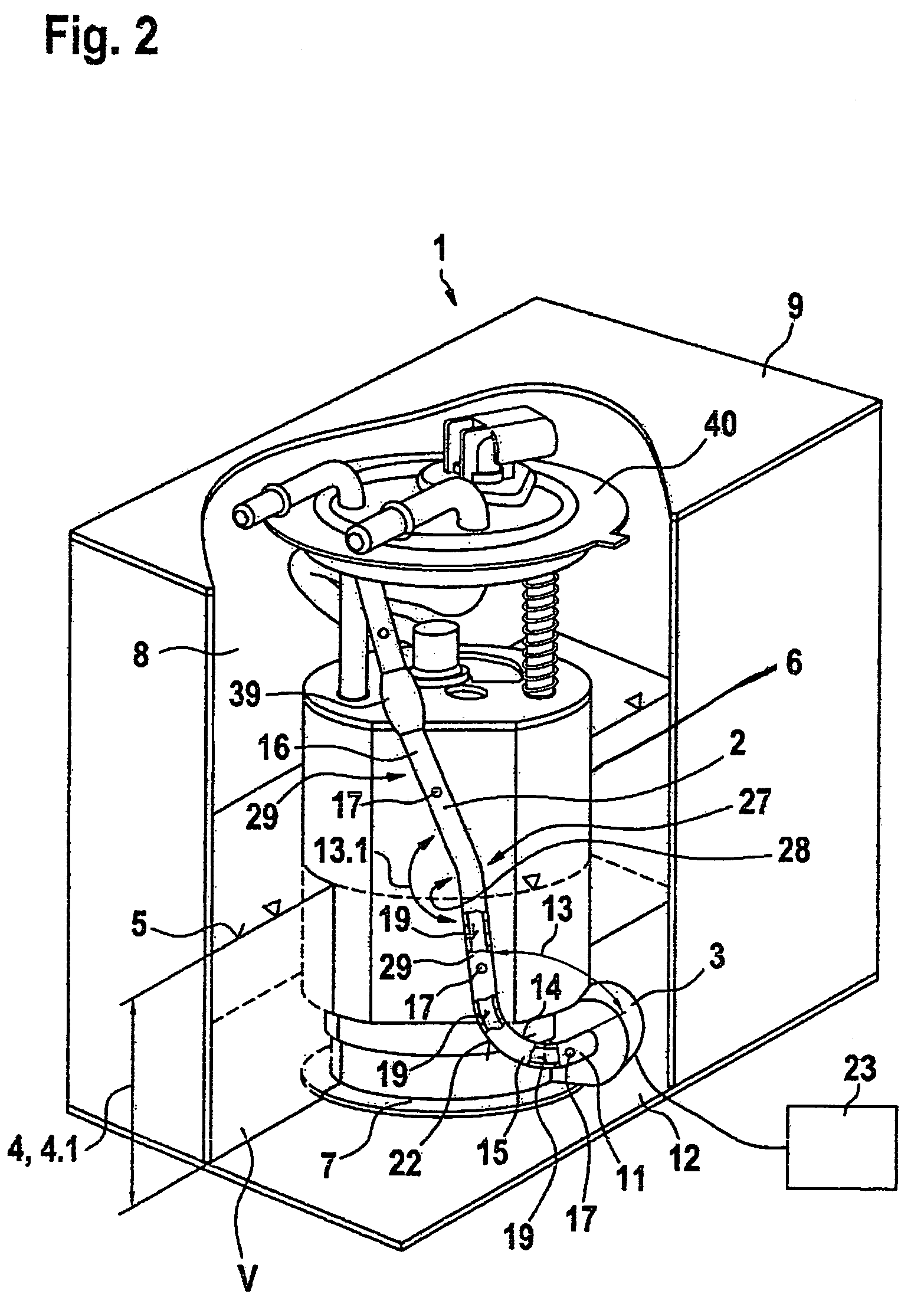
[0005]The device for measuring a fill level according to the invention, has the advantage over the prior art that an improvement is attained in a simple way, such that despite the possibility of measuring even the tiniest fill level heights, a simple disposition of the device in the container is possible, since the device of the invention is disposed on a fluid feeding device that protrudes into the container. As a result, the manufacturers of containers no longer need to provide mounts in or on the container for securing devices for measuring a fill level. Mounting the device of the invention on the fluid feeding device is substantially less expensive and simpler than mounting it on the container.
[0006]It is advantageous for the sound guide conduit and / or the ultrasonic transducer to be cast, glued, welded, clipped or screwed onto an outer circumference of the fluid feeding device, because these are especially inexpensive kinds of connections.
[0007]It is especially advantageous if following the forward-flow region, the sound guide conduit has at least one bend with a deflection and at least one straight region with a conduit slope angle, since in this way the transit time of the emitted sonic pulses can be adapted to the geometry of a given container. This is necessary because modern containers are constructed quite variably. From the transit time of the sonic pulse, the fill level is determined, and a conclusion about a fill volume is drawn by means of a characteristic curve stored in memory in an evaluation unit. Depending on the geometry of the container, an unfavorably great slope of the characteristic curve can occur. The great slope of the characteristic curve means a low sensitivity in measuring the fill level, since a slight change in the transit time of the sonic pulse means a major change in the fill volume. If the slope of the characteristic curve is great, an interval in the transit time from the minimally measurable fill level to the maximum fill level is small, making the sensitivity of measurement and hence the measurement precision less. By varying the number of bends and the number of straight regions, varying the angle of the deflection at a given bend, and varying the conduit slope angle of a given straight region of the sound guide conduit, it is possible for instance to adapt the transit time of the emitted sonic pulses, and hence the slope of the characteristic curve, in such a way that as much as possible over the entire range of the fill volume, high sensitivity and thus only a shallow slope of the characteristic curve are obtained. Especially at low fill levels, high sensitivity is necessary so that a driver of a motor vehicle will receive a precise, reliable fill level indication.

Problems solved by technology

Depending on the geometry of the container, an unfavorably great slope of the characteristic curve can occur.

Method used


Image

  • Device for measuring the level of a fluid in a fuel tank of a motor vehicle
  • Device for measuring the level of a fluid in a fuel tank of a motor vehicle
  • Device for measuring the level of a fluid in a fuel tank of a motor vehicle

Examples


Embodiment Construction

[0016]FIG. 1 shows a fluid feeding device, for instance a fuel pumping device, with a device according to the invention for measuring a fill level in a container, for instance a fuel tank of a motor vehicle. The device comprises a sound guide conduit 2 and a ultrasonic transducer 3. The sound guide conduit 2 and the ultrasonic transducer 3 are disposed on a fluid feeding device 6, which is inserted into a container such as a fuel tank 1.

[0017]The fuel feeding device 6 has at least one fuel pump, for instance an electric pump. However, it can also include other components, such as filter elements, pressure regulators, and check valves.

[0018]A fuel feeding device is disclosed for instance in German Patent Disclosure DE 44 35 508 A1 and in German Patent DE 196 17 496 C2, and the contents of these patent disclosures are hereby incorporated by reference.

[0019]As the fluid, fuel up to a fill level 4 is located in the fuel tank 1. The fuel in the fuel tank 1 has a fill volume V. At the hei...


PUM


Abstract

A device for measuring the level of a fluid in a container by means of a sound guide tube and an ultrasonic transducer disposed inside the container mounted in a fluid feeding device within the container.

Description

BACKGROUND OF THE INVENTION[0001]1. Field of the Invention[0002]The invention is based on a device for measuring a fill level of a liquid in a container.[0003]2. Description of the Prior Art[0004]A device for measuring a fill level is known from DE 199 42 378 A1, in which a ultrasonic transducer is disposed outside a fuel tank, near one end of a sound guide conduit that is provided between a container bottom and a top wall. The ultrasonic transducer sends ultrasonic waves into the sound guide conduit, and the ultrasonic waves are reflected at a surface of the fluid. The ultrasonic waves reflected are received by the ultrasonic transducer and evaluated in an evaluation unit. A fill level is ascertained from a transit time of the ultrasonic waves. A disadvantage of this is that a low level near the container bottom can no longer be measured, since when the level is low, the transit time of the emitted ultrasonic wave is so brief that the emitted ultrasonic wave has not yet decayed bef...

Claims


Application Information

Patent Timeline
IPC IPC(8): G01F23/00G01F23/28G01F23/296
CPCG01F23/2962
Inventor ROLLWAGE, MATHIASMARX, KLAUSTRAUB, PETERMUELDERS, STEFAN
Owner ROBERT BOSCH GMBH
Learn More