
Heat exchanging module and electronic device applying the same

a technology electronic device, which is applied in the direction of lighting and heating apparatus, cooling/ventilation/heating modification, electrical apparatus, etc., can solve the problems of affecting the operation performance and stability, consuming a lot of time, and affecting the efficiency of heat dissipation, etc., to enhance the yield of heat exchanging module, the effect of a lot of manufacturing time and high cos

Active Publication Date: 2017-07-11
DELTA ELECTRONICS INC
View PDF2 Cites 0 Cited by
  • Summary
  • Abstract
  • Description
  • Claims
  • Application Information

AI Technical Summary

Benefits of technology

The invention provides a heat exchanging module that can be stacked quickly and easily through a simple design. The module is composed of two kinds of structure, which can be stacked alternately to form a heat dissipating core. The first air guiding element is formed in a corrugated structure, which increases the rigidity and lifespan of the module and improves its heat exchanging performance. This invention simplifies the manufacturing process and reduces the cost compared to conventional methods.

Problems solved by technology

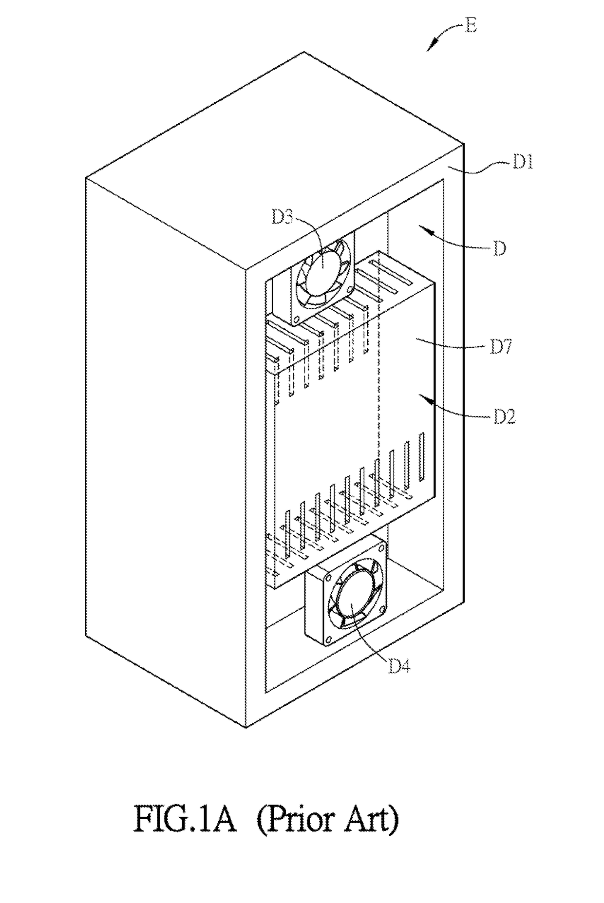
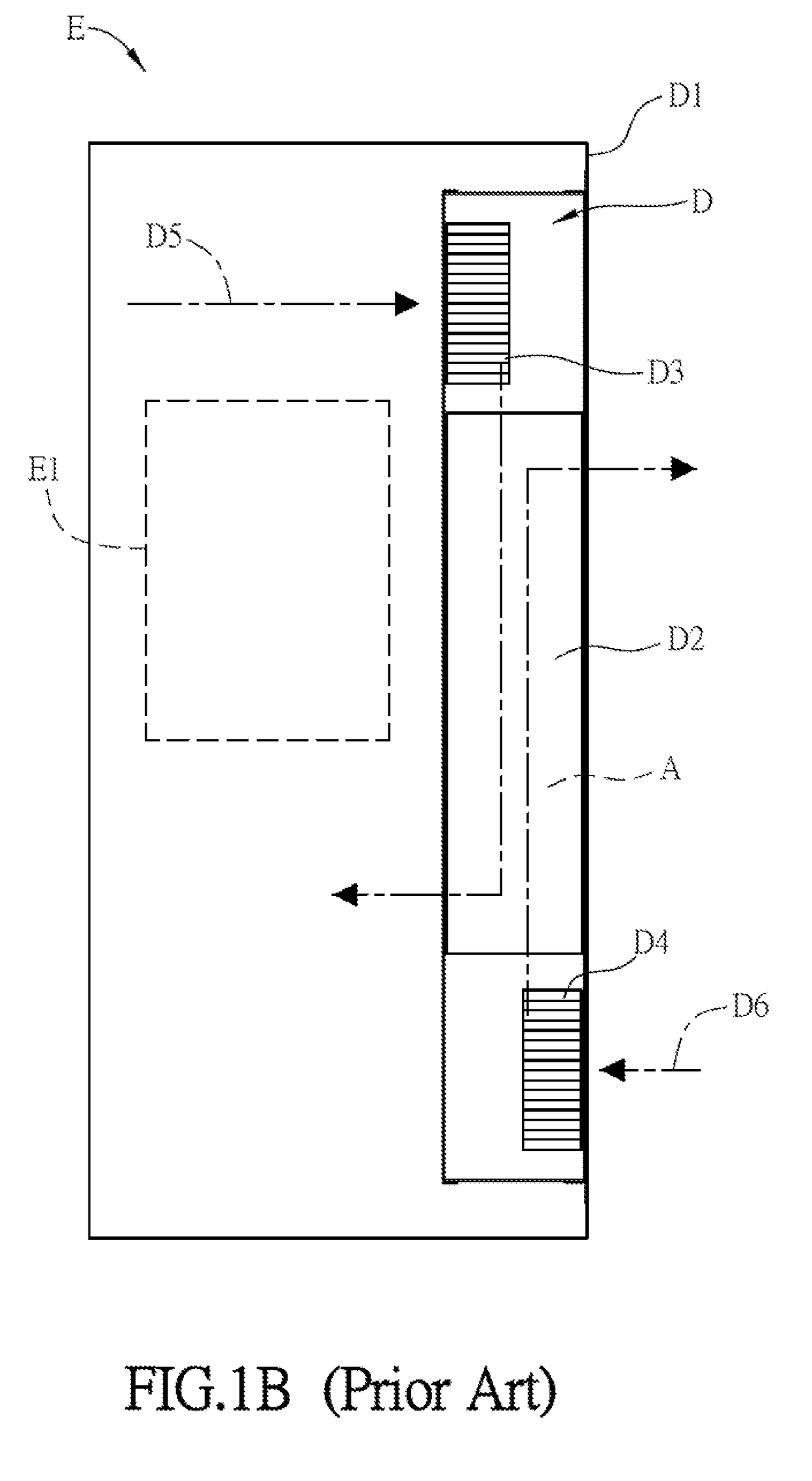
With the development of the electronic industry, the requirement of the operational speed and performance of the electronic device is raised, but the induced heat dissipating problem also becomes more serious and thus affects the operational performance and stability.
However, if only the passive-type heat dissipating method is used, the heat can't be dissipated immediately and effectively.
So, the assembly thereof is more complicated and takes much time.
Besides, the thin-type aluminum sheets are used to bring a better heat dissipating effect, but the thin-type aluminum sheets possess insufficient rigidity and will be easily bent and deformed.
Moreover, when the glues are not dried, the thin-type aluminum sheet are also easily displaced and tilted in the casing, so that the quality of the heat dissipating core composed of the conventional thin-type aluminum sheets is unstable.

Method used


Image

  • Heat exchanging module and electronic device applying the same
  • Heat exchanging module and electronic device applying the same
  • Heat exchanging module and electronic device applying the same

Examples


Embodiment Construction

[0040]The present invention will be apparent from the following detailed description, which proceeds with reference to the accompanying drawings, wherein the same references relate to the same elements.

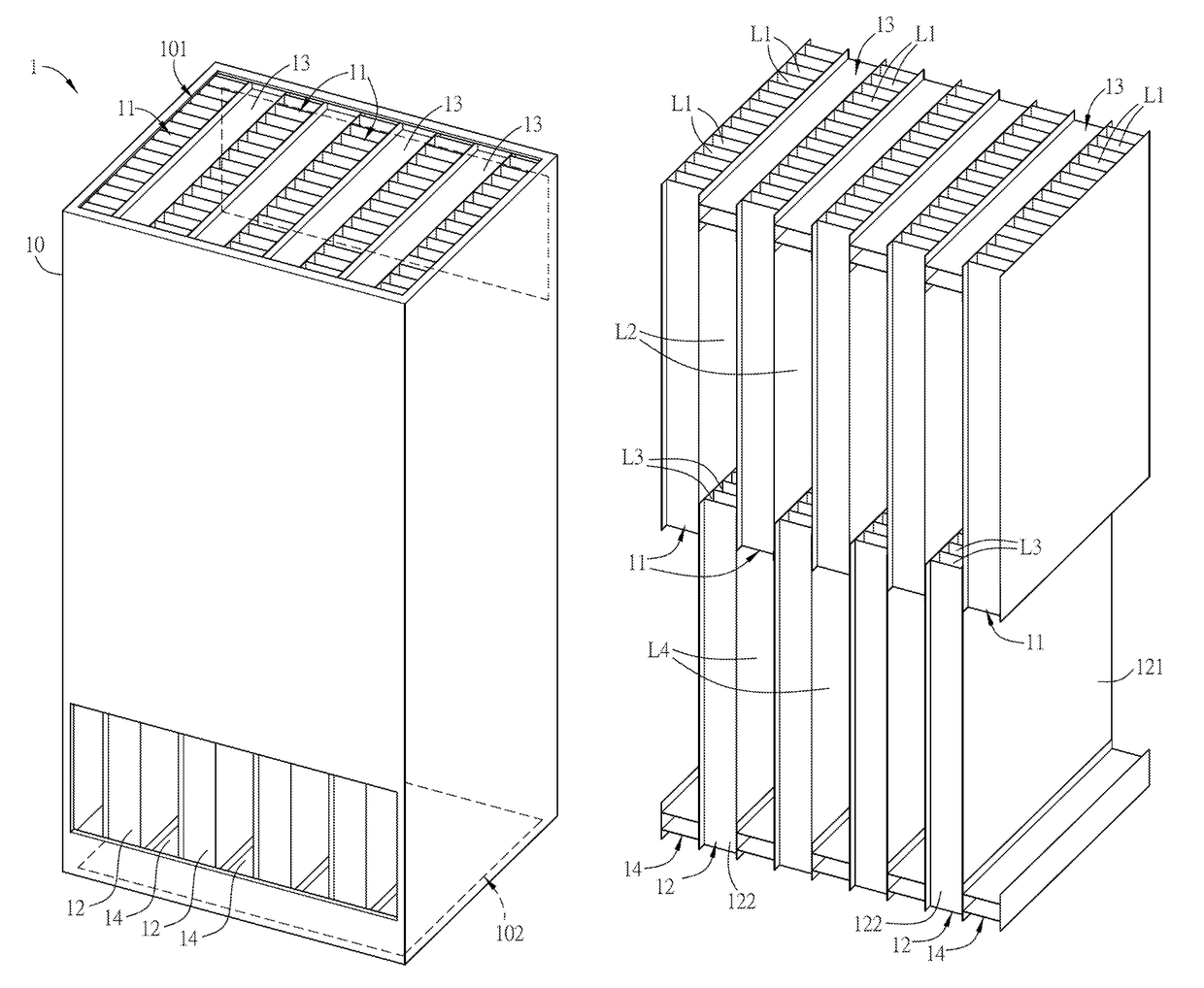
[0041]FIG. 2A is a schematic diagram of a heat exchanging module of an embodiment of the invention, FIG. 2B is a schematic diagram showing a part of the heat exchanging module in FIG. 2A, and FIG. 2C is a schematic exploded diagram of a part of the heat exchanging module in FIG. 2A. As shown in FIGS. 2A to 2C, the heat exchanging module 1 includes a casing 10, a plurality of first air guiding elements 11, a plurality of second air guiding elements 12, a plurality of first separation elements 13 and a plurality of second separation elements 14, and the first air guiding elements 11, the second air guiding elements 12, the first separation elements 13 and the second separation elements 14 are disposed in the casing 10. In this embodiment, the casing 10 is a cuboid structure including a ...


PUM


Abstract

A heat exchanging module comprises a casing, a plurality of first air guiding elements and a plurality of first separation elements. The first air guiding elements are disposed in the casing. Each of the first air guiding elements comprises a plurality of first structures and a plurality of second structures, the first structures are disposed parallelly, and the second structures are disposed between the first structures and connected with the first structures to form a plurality of first channels. Each of the first separation elements is disposed between the two adjacent first air guiding elements to form a second channel. An airflow direction of the first channels is different from that of the second channels. The present invention further provides an electronic device using the same.

Description

CROSS REFERENCE TO RELATED APPLICATIONS[0001]This Non-provisional application claims priority under 35 U.S.C. §119(a) on Patent Application No(s). 104109331 filed in Taiwan, Republic of China on Mar. 24, 2015, the entire contents of which are hereby incorporated by reference.BACKGROUND OF THE INVENTION[0002]Field of Invention[0003]The invention relates to a heat exchanging module and an electronic device applying the same and, in particular, to a heat exchanging module and an electronic device applying the same which can reduce the assembly time and cost.[0004]Related Art[0005]With the development of the electronic industry, the requirement of the operational speed and performance of the electronic device is raised, but the induced heat dissipating problem also becomes more serious and thus affects the operational performance and stability. For the normal operation of the electronic device, the electronic device is generally configured with a heat dissipating device so that the heat...

Claims


Application Information

Patent Timeline
Patent Type & Authority Patents(United States)
IPC IPC(8): H05K7/20F28F3/02F28D9/00
CPCH05K7/202F28D9/0062F28F3/025
Inventor CHEN, LEE-LONGLI, WU-CHI
Owner DELTA ELECTRONICS INC
Learn More