Variable rail safety system

a safety system and variable technology, applied in the field of safety devices, can solve the problems of prior art products, falling objects on the lower level of the construction site, and workers falling and risking injury or death

Inactive Publication Date: 2005-11-10
KLEIN RICHARD JAMES +1
View PDF7 Cites 19 Cited by
  • Summary
  • Abstract
  • Description
  • Claims
  • Application Information

AI Technical Summary

Benefits of technology

[0012] an elongate brace member having spaced first and second brace attachment means, said first brace attachment means adaped to be pivotally engaged with said second base attachment means, and said second brace attachment means adapted to be selectively

Problems solved by technology

There have been problems providing safety rails to areas under construction such as floor edges, roof edges, and tops of walls as they are being erected prior to the floor being installed, as well as for openings in roofs, floors and stairwells.
These types of guard rails, also referred to as fences or railings, are usually not as strong as one would like, and a worker falling against such railings can easily dislodge the makeshift railing causing the worker to fall and risk injury or death.
The dislodged makeshift railing may also fall down, creating a falling object hazard for lower levels of the construction site.
These problems are of such a nature that the Occupational Safety and Health Administration, or OSHA, in the United States of America and the Occupational Health and Safety Code, or OHS code, in Canada have become alarmed.
However, there are disadvantages to these prior art products.
Some disadvantages of the products of example 1 are that they tend to be heavy units making it very hard for the carpenter to carry the units over the open framing members of a roof and to install the guard rail system.
Further, the design of the support in Canadian patent application 2,162,526 limits the choice of horizontal rail members for installation as railings.
Yet a further disadvant

Method used


Image

  • Variable rail safety system
  • Variable rail safety system
  • Variable rail safety system

Examples


Embodiment Construction

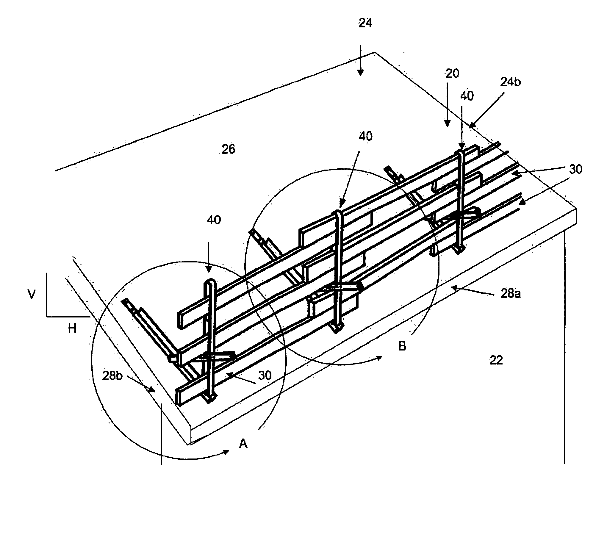
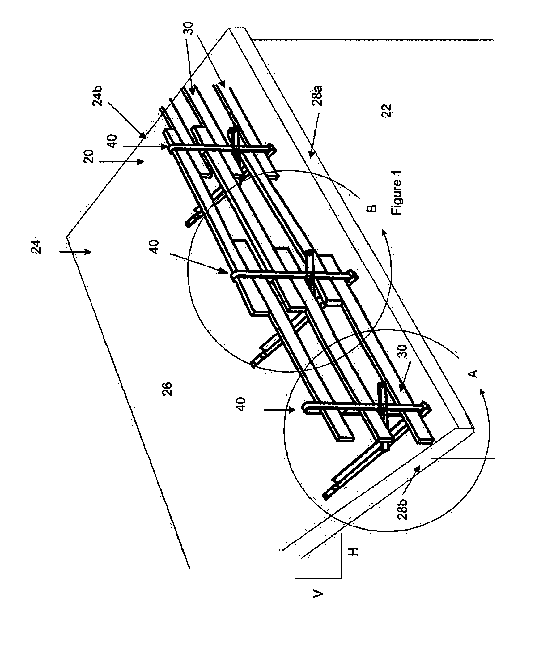
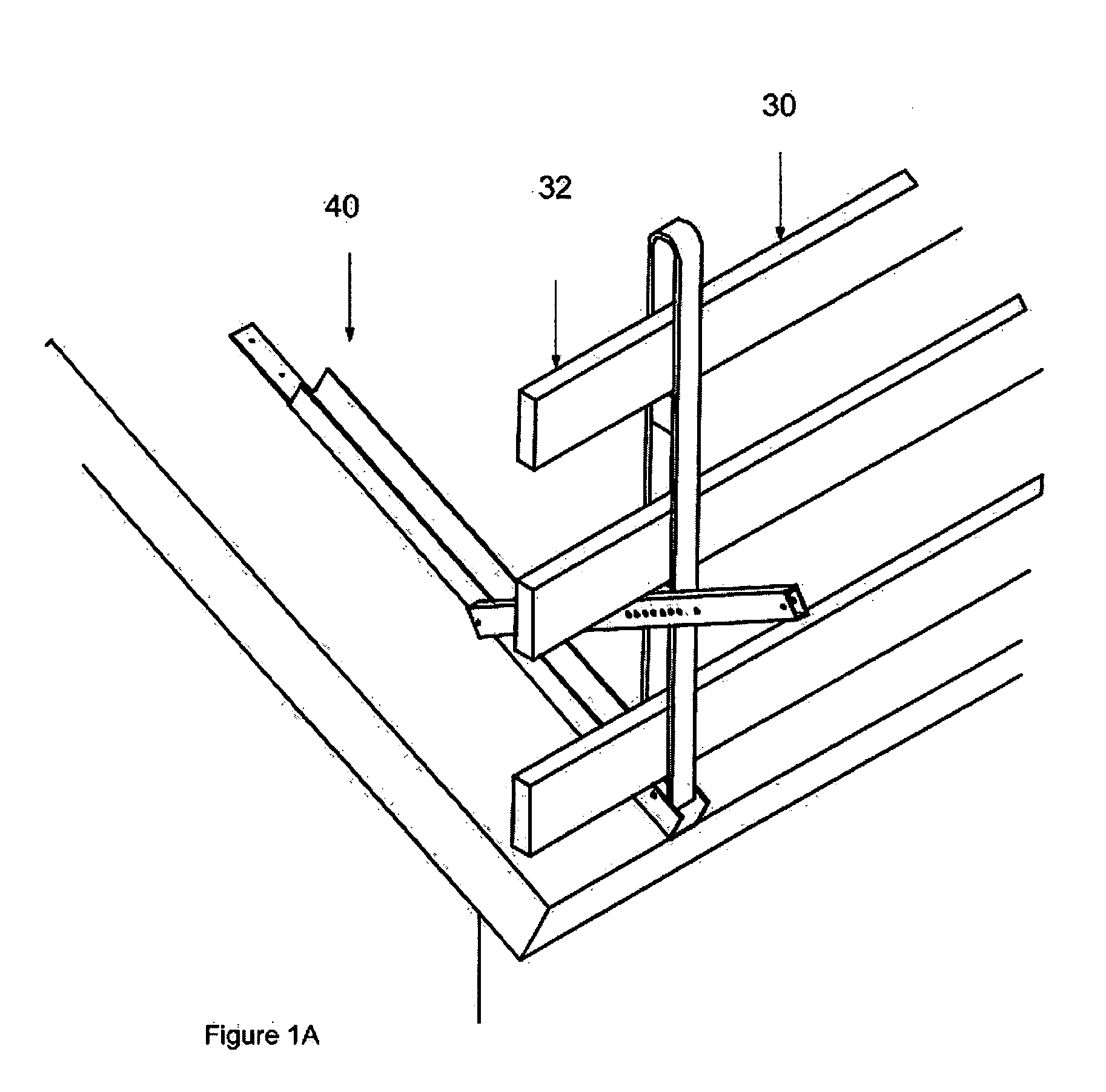
[0048] The figures show a guard rail system and assembly according to the present invention, which is also referred to herein as a variable rail safety system, or simply the “VRS system”. Referring first to FIGS. 1 to 1b, the VRS system is defined by a guard rail fence (generally designated by the reference numeral 20) which is capable of being removably attached to various structures, most commonly to a building 22 under construction, to provide a safe working area. One such structure for illustrative purposes is an inclined or pitched roof 24 having a timber truss sub-structure (not shown) covered by plywood or like sheeting 26. The VRS system should be installed wherever a fall barrier is required, such as along the front and / or side edges 28a, 28b of the roof. Other structures will be shown and discussed later.

[0049] Referring still to the embodiment shown in FIGS. 1-1b, the guard rail fence 20 is formed by removably attaching several elongate rail supports 40 to the roof at sp...


PUM


Abstract

A multi-use variable guard rail system for providing a safe working area is mountable on various surfaces, whether sloped (roofs), vertical (walls) or horizontal (floors). A rail support of the system has an upright pivotally engaged with a base, and a brace that locks the upright relative to the base in numerous positions ranging between an acute angle and an obtuse angle where the upright and base are linearly aligned. The upright has openings that hold rails such as various sizes of lumber in a vertically stacked array without the need to cut or fasten the lumber, and which allows for replacement of rails without disassembly of the rest of the system. The base has a tongue particularly suited for roof work, namely it is used to mount the rail support to the roof, yet allows the base to be lifted for placing shingles thereunder.

Description

FIELD OF THE INVENTION [0001] The present invention relates to a safety device and more particularly to a temporary, multi-use guard rail system to provide a safe working area for persons on a building under construction. BACKGROUND OF THE INVENTION [0002] When a residential or commercial building is in the various stages of construction, there is a need to have a safe work area. There have been problems providing safety rails to areas under construction such as floor edges, roof edges, and tops of walls as they are being erected prior to the floor being installed, as well as for openings in roofs, floors and stairwells. [0003] The current practice is to merely construct a makeshift guard rail from lumber (such as lumber of a nominal 2″×4″ inch (aprox. 50 mm×100 mm) cross-section, commonly referred to as a “two-by-four” or “2×4”). These types of guard rails, also referred to as fences or railings, are usually not as strong as one would like, and a worker falling against such railing...

Claims


Application Information

Patent Timeline
IPC IPC(8): E04G1/36E04G21/32E04H17/00
CPCE04G21/3219E04G21/3214
Inventor KLEIN, RICHARD JAMESKLEIN, VICTOR DEE
Owner KLEIN RICHARD JAMES
Why Eureka
Try Eureka