Wall-mounted ultrasonic humidifier

a humidifier and ultrasonic technology, which is applied in the field of humidifiers, can solve the problems of inconvenient use of humidifiers, unusually large size of general humidifiers used in home and office, and uneven mist emitted by humidifiers, etc., and achieves the effects of convenient assembly and installation, convenient mounting, and easy separation

Inactive Publication Date: 2005-11-10
KIM YOUNG OH
View PDF7 Cites 12 Cited by
  • Summary
  • Abstract
  • Description
  • Claims
  • Application Information

AI Technical Summary

Benefits of technology

[0006] A second object of the present invention is to provide a humidifier that can be easily assembled and installed.
[0007] A third object of the present invention is to provide a transducer, which can be easily separated from the humidifier and easily mounted thereto, in order to facilitate the maintenance of the transducer (e.g., repair or cleaning).

Problems solved by technology

A conventional general humidifier, which is used in home and offices, has an unusually large size due to the size of the water tank inside the humidifier.
In such a case, however, the water supply to the humidifier has to be performed more frequently as the size of the water tank is reduced, thus making it inconvenient to use the humidifier.
If the humidifier is placed on the floor of a room, then the mist emitted from the humidifier is not distributed evenly throughout the room or the humidifier may be knocked down by the users' activities in the room.
For these reasons, the humidifier placed on the floor cannot be expected to perform its essential function well.
However, since the mist cannot be optimally distributed at this height, the humidifiers are often placed at the center of the room in order for the mist to be more evenly distributed throughout the room.

Method used


Image

  • Wall-mounted ultrasonic humidifier
  • Wall-mounted ultrasonic humidifier
  • Wall-mounted ultrasonic humidifier

Examples


Embodiment Construction

[0017] A preferred embodiment of the present invention will now be described below with reference to accompanying drawings.

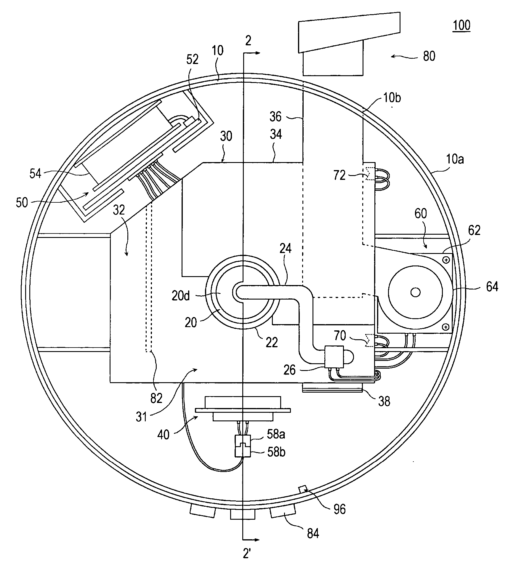
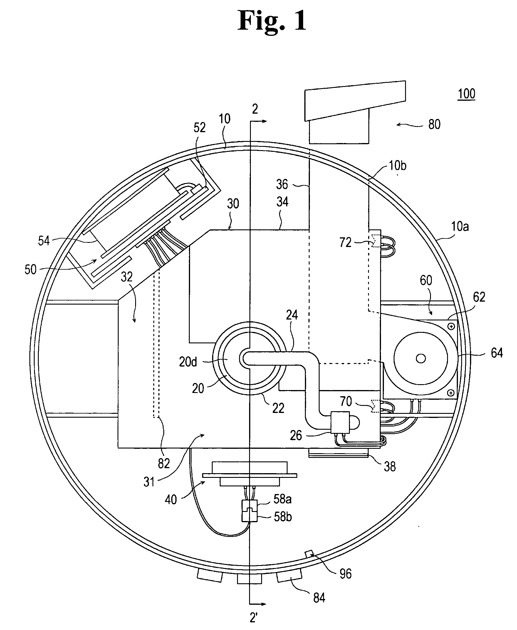
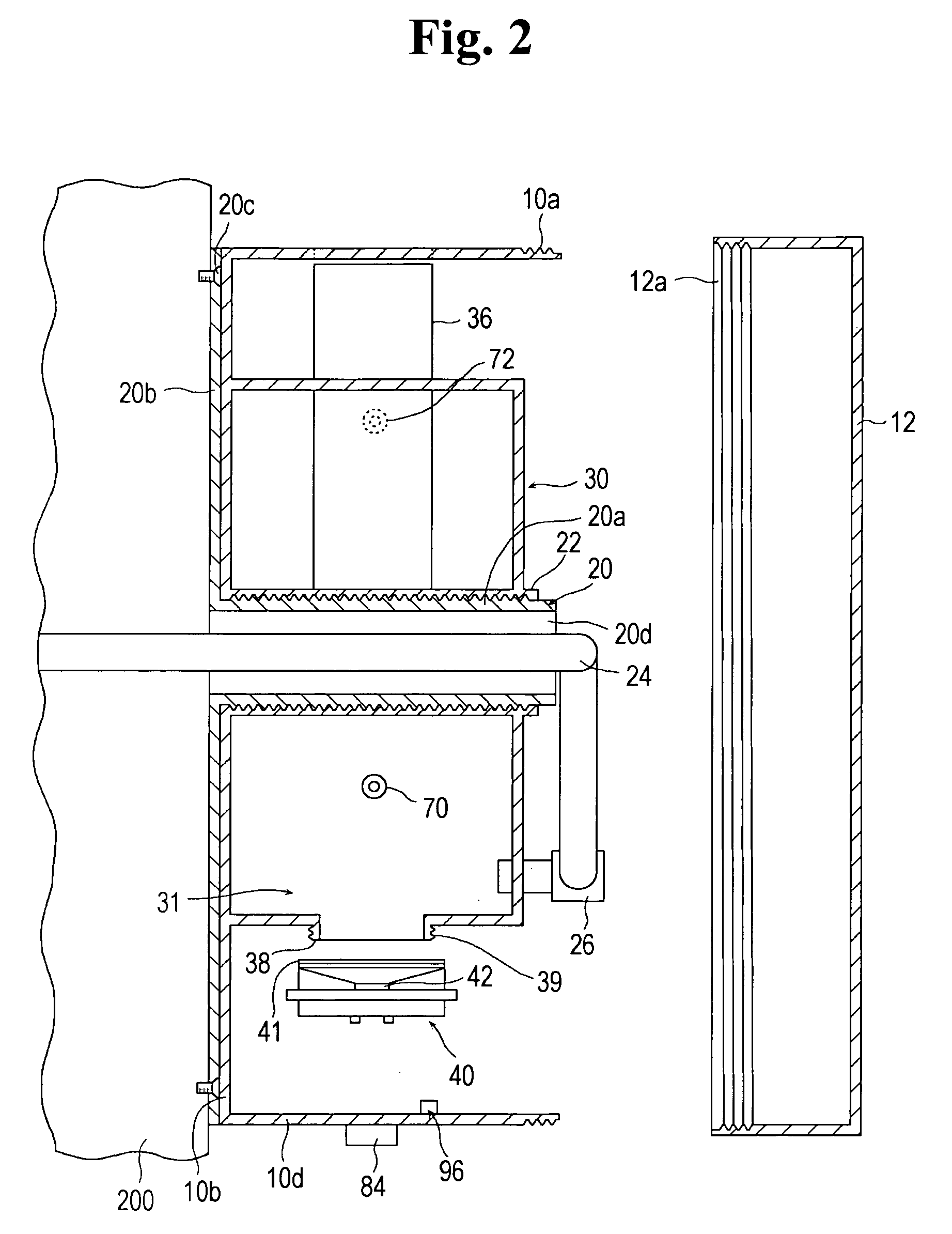
[0018] Referring to FIGS. 1 and 2, a humidifier 100 of the present invention includes a cylindrical body 10 having various components therein, The humidifier 100 of the present invention further includes a base 20 mounted to a wall 200 and engaged with the cylindrical body 10 through a thread engagement therebetween.

[0019] As illustrated in FIG. 2, the cylindrical body 10 includes a mounting plate 10b, which comes into contact with the flange 20b, and a side wall 10d perpendicularly extending from the mounting plate 10b. A water tank 30 is formed on the mounting plate 10b. A boss 22 is formed through the mounting plate 10b and the water tank 30, and is provided with a female thread formed thereinside.

[0020] The base 20 has a hollow thread tube 20a having a male thread on its external surface, which can be engaged with the female thread, and a flange 20b perpe...


PUM


Abstract

There is provided a humidifier comprising: a base including a plate member mounted on a wall and a support member perpendicularly extending from the plate member; a body having a mounting plate and a side wall member perpendicularly extending from the mounting plate, wherein a boss protrudes from the mounting plate and is formed through the mounting plate, and wherein the boss is fitted around the support member; a water tank formed on the mounting plate and having a storage space for storing water therein, the water tank further having a discharging passageway communicating with an outside of the humidifier; a water-supply tube connected to a water source at its one end while other end thereof is connected to the water tank; a transducer for converting the water in the water tank into mist; and a blower for providing an air flow which moves the mist to the outside through the discharging passageway. An automatic water-feeding system is provided in the humidifier.

Description

FIELD OF THE INVENTION [0001] The present invention generally relates to a humidifier, and more particularly to a wall-mounted ultrasonic automatic water-feeding humidifier having a base and a body, which can be assembled with each other through a thread engagement between a male thread of the base and a female thread of the body, thereby allowing an easy installation of the humidifier on the wall side as well as a transducer configured to be easily removed from and mounted to the humidifier. BACKGROUND OF THE INVENTION [0002] A conventional general humidifier, which is used in home and offices, has an unusually large size due to the size of the water tank inside the humidifier. Reducing the size of the water tank used in the humidifier is desirable in order to reduce the size of the humidifier. In such a case, however, the water supply to the humidifier has to be performed more frequently as the size of the water tank is reduced, thus making it inconvenient to use the humidifier. [...

Claims


Application Information

Patent Timeline
Patent Type & Authority Applications(United States)
IPC IPC(8): B01F3/04F24F6/12
CPCF24F6/12Y02B30/80F24F2006/125Y02B30/70F24F2221/32
Inventor KIM, YOUNG-OH
Owner KIM YOUNG OH
Why Eureka
Try Eureka