Method for on-line monitoring of condition of non-aqueous fluids

a non-aqueous fluid, online monitoring technology, applied in the direction of resistance/reactance/impedence, instruments, material impedance, etc., can solve the problems of -line laboratory tests which are often not cost and/or time-effective for equipment operators, reducing engine life and performance,

Inactive Publication Date: 2005-11-10
THE LUBRIZOL CORP
View PDF14 Cites 9 Cited by
  • Summary
  • Abstract
  • Description
  • Claims
  • Application Information

AI Technical Summary

Benefits of technology

[0013] Another feature of the invention is that the fluid response can be measured by controlling the fluid temperature to an essentially fixed temperature or can be converted or corrected to minimize the effect of temperature variation on fluid response using appropriate formulae or look-up tables.
[0016] Another feature of the invention is that the average response rate increase as a function of fluid use can be fixed, can be updated by external input or can be determined by averaging the fluid response change over an initial period of fluid use.
[0017] Another feature of the invention is that essentially complete fluid exchanges made to the equipment can be determined without need for additional input in order to reset the fluid condition and quality thresholds for the fresh fluid added to the equipment.
[0019] Another feature of the invention is that the invention can provide an output to memory for later download, to a signaling device than can be observed or received by, for example an operator, to a service facility or function, to a signal processor that converts the output to another output, or combinations thereof.

Problems solved by technology

Using a lubricant past the end of its useful life reduces engine life and performance and possibly leads to catastrophic engine failure.
However, due to the complexity of lubricant degradation, which can be a function of engine age, operating conditions and other factors, accurate determination of lubricant condition has traditionally required off-line laboratory tests which often are not cost and / or time effective for equipment operators.
An issue with estimates or algorithms that use no lubricant condition measurement or specific information about the quality of the lubricant in the engine is that lubricant change decisions are made without knowing either actual condition or even potential useful life.
In general, sensors that do not provide a “fluid condition” output are of limited value to engine / equipment manufacturers who do not know the relationship, if any, between sensor signal and fluid condition.
A limitation is that while the described sensor may measure lubricant soot content, the sensor does not determine if or when the lubricant begins to lose effectiveness in controlling the soot; that is, the point at which the additional soot content results in increased size of dispersed particles.
A loss of a lubricant's ability to control soot, or more generally contaminants, is typically first identified by increased fluid viscosity, but typically occurs before a rapid viscosity increase is noted and, in any case leads, to reduced performance and service life of the engine.

Method used


Image

  • Method for on-line monitoring of condition of non-aqueous fluids
  • Method for on-line monitoring of condition of non-aqueous fluids
  • Method for on-line monitoring of condition of non-aqueous fluids

Examples


Embodiment Construction

[0033] The invention relates to a method for on-line monitoring and / or detecting condition of a highly resistive fluid used in industrial and transportation. The highly resistive fluid is a non-aqueous fluid, that is, not water based, and substantially water free. The non-aqueous fluid may, however, contain water contaminants.

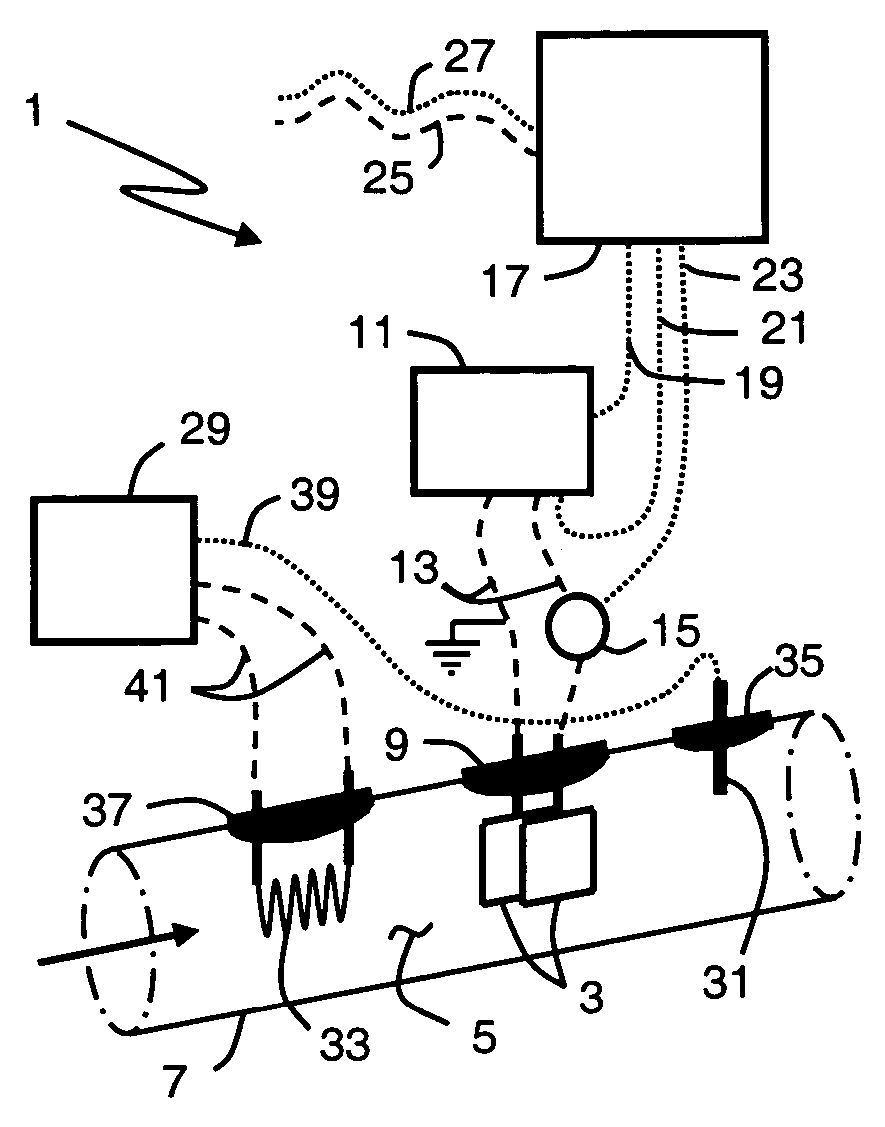
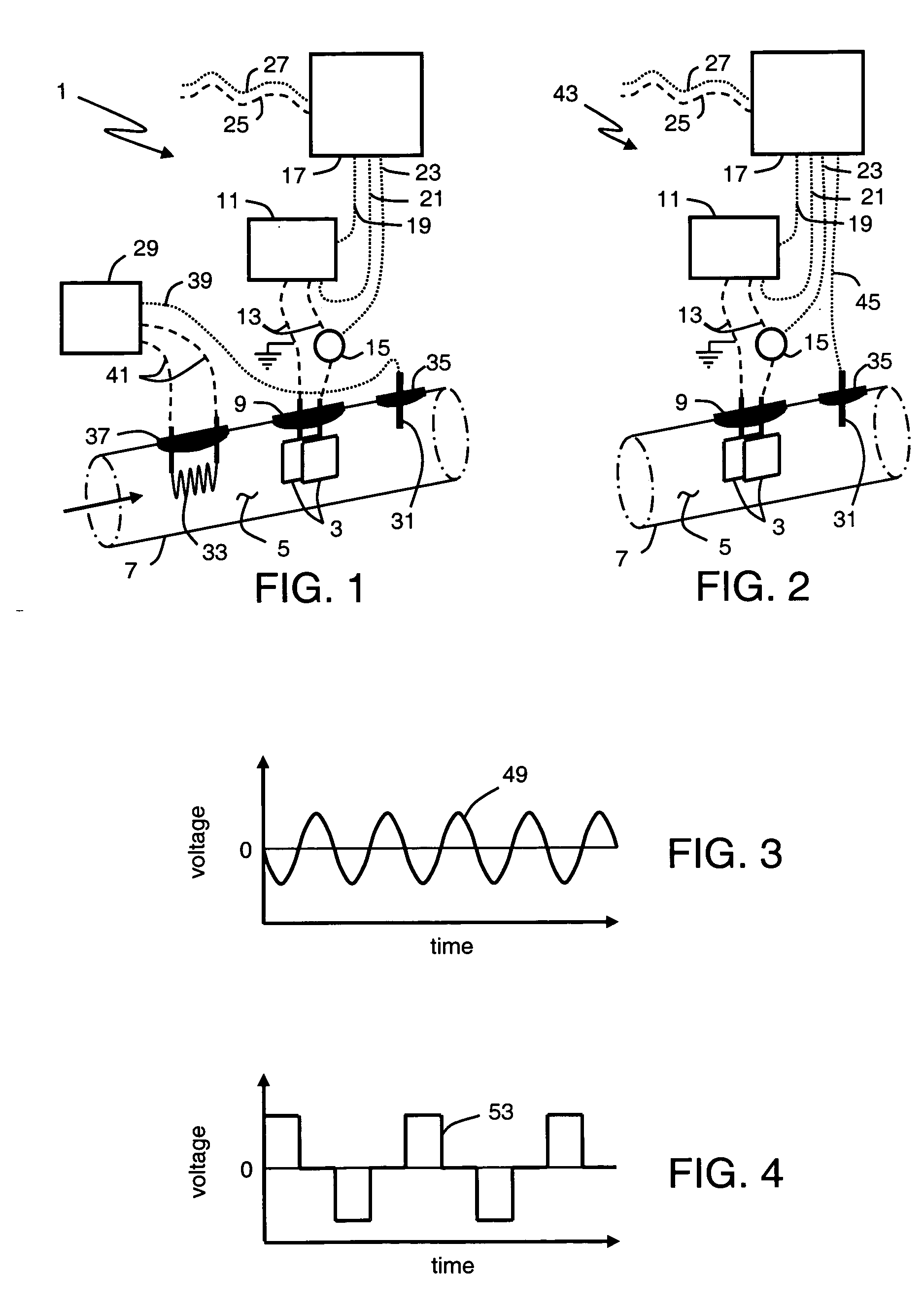
[0034]FIG. 1 is a schematic illustration of an apparatus 1 that can be used to collect appropriate data required for the on-line monitoring and detecting condition of a fluid. Apparatus 1 includes essentially parallel electrodes 3 immersed in highly resistive fluid 5, in conduit 7. Electrodes 3 are fixedly held and electrically isolated by mounts 9. Apparatus 1 also includes signal generator 11 that supplies a high-frequency voltage signals of fixed amplitude and frequency through electrical conduits 13, to electrodes 3. The voltage signal supplied by signal generator 11 can be an essentially sine wave signal as shown in FIG. 3 where the voltage signal oscilla...


PUM

PropertyMeasurementUnit
frequencyaaaaaaaaaa
temperatureaaaaaaaaaa

Abstract

A method for determining condition of a highly resistive fluid in transportation and industrial equipment. The method uses apparatus that applies a high frequency oscillating voltage signals to electrodes immersed in the fluid and quantifies fluid response to the signals. Apparatus can further include means to control the temperature of the fluid, or a temperature sensor to monitor the temperature of fluid at the electrodes. The method monitors response of the fluid to the electrical signal applied by the apparatus. The frequency of the applied signal for the method is predetermined as a function of apparatus electrode geometry, fluid temperature or temperature range, and chemical composition of the fluid being monitored. The magnitude of fluid response relative to initial and the rate of change of the fluid response as a function of equipment use are used to essentially continuously determine fluid condition while in use. In particular, the method can determines approximate contaminant content of the fluid and can determine when the fluid has reached the end of its useful life due to the approximate contaminant content and / or due to loss or ability to disperse additional contaminants as very finely divided suspended particles. For apparatus or applications where the monitored fluid is not controlled to constant temperature, the method includes correcting the temperature sensitive fluid responses for temperature variations for the fluid quality and condition determination. The method can also include determining when essentially complete fluid exchanges are made to the equipment without need for additional input.

Description

BACKGROUND OF THE INVENTION [0001] The present invention is a method for monitoring the condition of a highly resistive fluid(s) while in use in transportation or industrial equipment including but not limited to vehicles, machines, devices and the like. The invention has particular benefit for on-line monitoring and analysis of a diesel engine lubricant condition. More specifically, the invention has benefit in monitoring soot content of a diesel engine lubricant and in determining when the lubricant loses the ability to control the soot content for optimum engine performance and life. [0002] Lubricating oil is critical to the life and performance of an internal combustion engine. When the lubricant has appropriate viscosity for the required hydrodynamic film, detergents and dispersants to suspend and / or neutralize undesired contaminants, and surface active chemicals to protect engine component surfaces, the lubricant allows for long, efficient engine operation by reducing friction...

Claims


Application Information

Patent Timeline
Patent Type & Authority Applications(United States)
IPC IPC(8): G01N27/06G01N27/22G01N33/28
CPCG01N33/2888G01N33/28G01N27/22G01N27/06G01N27/02
Inventor BOYLE, FREDERICK P.LVOVICH, VADIM F.
Owner THE LUBRIZOL CORP
Why Eureka
Try Eureka