System and method for luminance degradation reduction using thermal feedback

Inactive Publication Date: 2005-11-10
VISTEON GLOBAL TECH INC
View PDF9 Cites 22 Cited by
  • Summary
  • Abstract
  • Description
  • Claims
  • Application Information

AI Technical Summary

Benefits of technology

[0006] In satisfying the above need, as well as overcoming the enumerated drawbacks and other limitations of the related art, the present invention provides a system to compensate for luminance degradation of an emissive display. As its primary components, the system includes a controller and a temperature sensor. The controller is coupled to the emissive display to provide a driving signal thereby controlling the display luminance. The temperature sensor is located proxi

Problems solved by technology

Therefore, these displays are thin and very compact.
However, emissive display technologies, such as OLED displays, suffer from differential aging, and must be carefully analyzed and used to ensure that lifetime expectations are met.
Si

Method used


Image

  • System and method for luminance degradation reduction using thermal feedback
  • System and method for luminance degradation reduction using thermal feedback
  • System and method for luminance degradation reduction using thermal feedback

Examples


Embodiment Construction

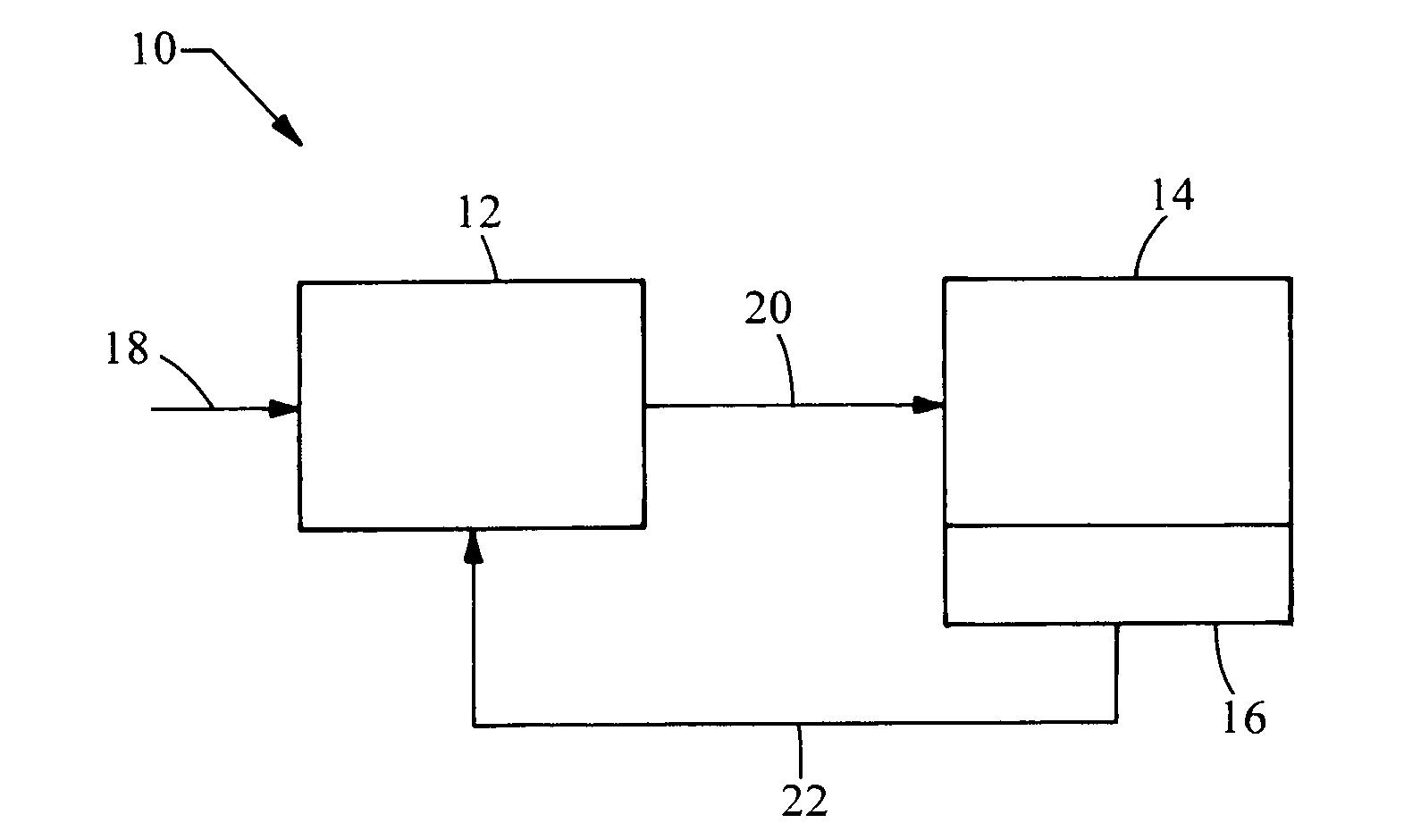
[0018] Referring now to FIG. 1, a system embodying the principles of the present invention is illustrated therein and designated at 10. As its primary components, the system 10 includes a control circuit 12, an emissive display 14, and a temperature sensor 16. A desired luminance signal 18 is provided to the control circuit 12, the desired luminance signal 18 is often generated from a display brightness control (not shown). The control circuit 12 generates a display drive signal 20 based on the desired luminance signal 18. The display drive signal 20 is provided to the emissive display 14, causing the emissive display 14 to operate at a specific display luminance level. The temperature sensor 16 is located proximate the emissive display 14 and configured to monitor a temperature of the emissive display 14. The temperature sensor 16 generates a feedback signal 22 which is received by the control circuit 12. The feedback signal 22 is indicative of the temperature measured by the tempe...


PUM


Abstract

A system to compensate for luminance degradation of an emissive display is provided. As its primary components, the system includes a controller and a temperature sensor. The controller is coupled to the emissive display to provide a driving signal thereby controlling the display luminance. The temperature sensor is located proximate the emissive display and is in electrical communication with the controller. The controller receives a temperature signal from the temperature sensor and varies the luminance based on the temperature signal. As the temperature of the emissive display increases, the controller reduces the display luminance according to a transfer function. The transfer function may have a linear term and/or a non-linear term relating the operating luminance to the display temperature.

Description

BACKGROUND [0001] 1. Field of the Invention [0002] The present invention generally relates to a system and method to compensate for luminance degradation using thermal feedback. [0003] 2. Description of Related Art [0004] In the portable display industry, much excitement has been generated surrounding the use of organic light emitting diode (OLED) displays. OLED displays are self-luminous and do not require backlighting. Therefore, these displays are thin and very compact. OLED displays have a wide viewing angle and generally require very little power. However, emissive display technologies, such as OLED displays, suffer from differential aging, and must be carefully analyzed and used to ensure that lifetime expectations are met. Differential aging is where portions or colors of the display used more frequently emit a lower luminance than portions used less frequently. Light valve technology such as liquid crystal, interferometric modulator, LCOS, micro-mirror, and electrophoretic d...

Claims


Application Information

Patent Timeline
IPC IPC(8): H01L51/50G09G3/04G09G3/12G09G3/20G09G3/22G09G3/30G09G3/32H05B33/14
CPCG09G3/3208G09G2320/0626G09G2320/043G09G2320/041G09G3/32
Inventor LUTHER WEINDORF, PAUL FREDRICK
Owner VISTEON GLOBAL TECH INC
Why Eureka
Try Eureka