Transmission liquid crystal display device

a liquid crystal display and liquid crystal technology, applied in the field of transmission liquid crystal display devices, can solve the problems of inability to reduce power consumption, and achieve the effect of reducing light intensity and power consumption

Inactive Publication Date: 2012-06-12
SHARP KK
View PDF16 Cites 4 Cited by
  • Summary
  • Abstract
  • Description
  • Claims
  • Application Information

AI Technical Summary

Benefits of technology

[0016]The present invention was made in view of the foregoing problems, and an object of the present invention is to realize a transmission liquid crystal display device which can achieve further reduction of power consumption by reducing intensity of light absorbed not only by the liquid crystal panel but also by the color filter.
[0018]According to the arrangement, by using the liquid crystal panel in which a pixel is divided into four sub pixels as R, G, B, and W sub pixels, it is possible to partially incorporate R, G, and B components into the W sub pixel having no (or little) loss of light absorbed by the filter. As a result, it is possible to reduce light absorbed by the color filter, so that it is possible to realize reduction of power consumption of the transmission liquid crystal display device.
[0019]Note that, the liquid crystal panel in which a pixel is divided into four sub pixels lowers a display luminance of a pixel where light intensity of the sub pixels can be hardly incorporated into the W sub pixel. Thus, in case where the liquid crystal panel is combined with a normal backlight which cannot control an emission luminance, it is impossible to reduce power consumption. However, by combining the liquid crystal panel with a white active backlight, it is possible to reduce power consumption of the white active backlight.

Problems solved by technology

Thus, in case where the liquid crystal panel is combined with a normal backlight which cannot control an emission luminance, it is impossible to reduce power consumption.

Method used


Image

  • Transmission liquid crystal display device
  • Transmission liquid crystal display device
  • Transmission liquid crystal display device

Examples


embodiment 1

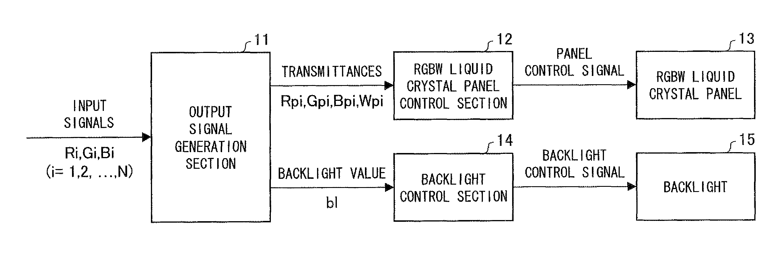
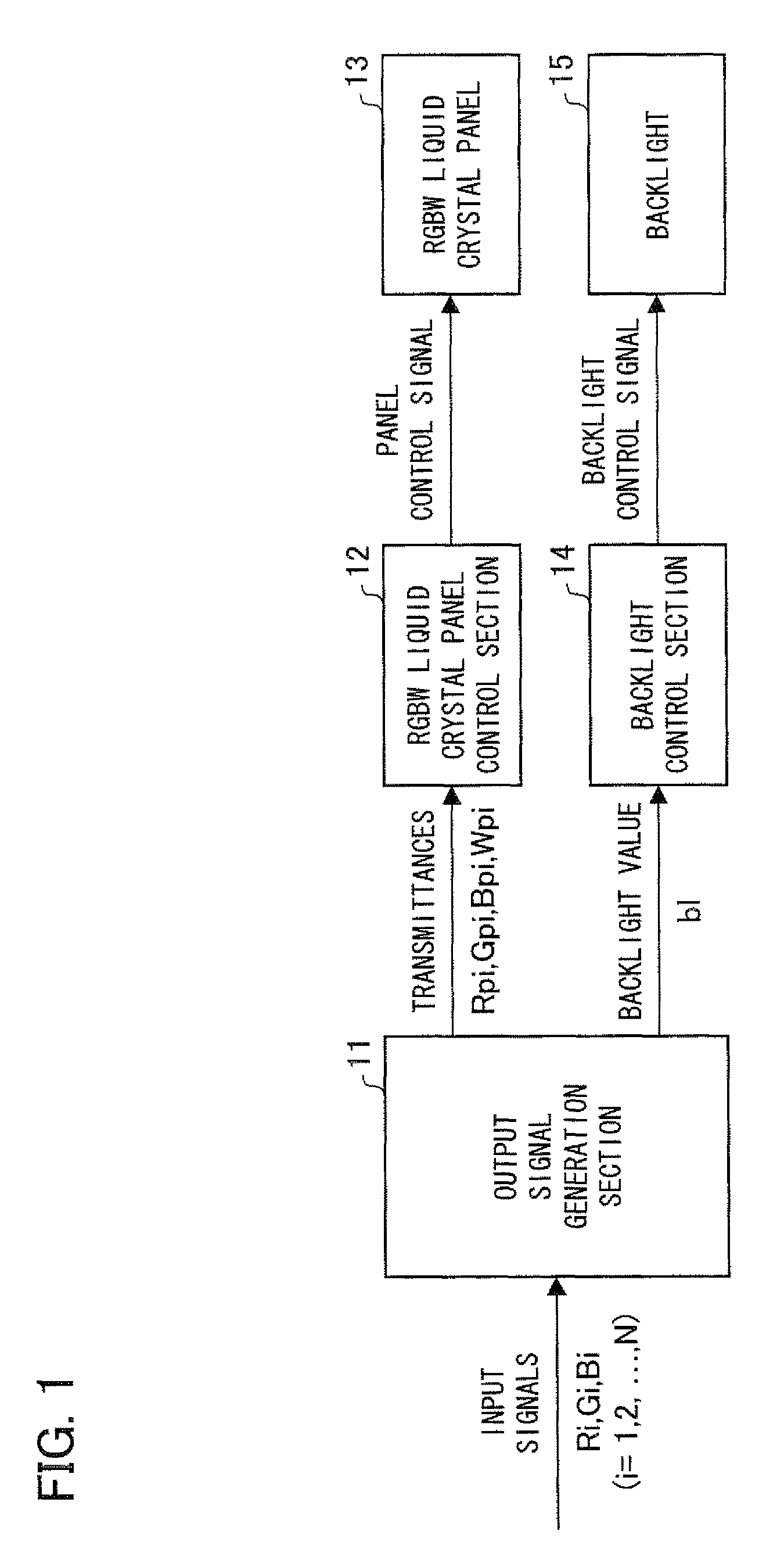
[0037]The following description will explain one embodiment of the present invention with reference to FIG. 1 to FIG. 10. First, with reference to FIG. 1, a schematic arrangement of a liquid crystal display device according to the present embodiment (hereinafter, referred to as the present liquid crystal display device) is described as follows.

[0038]The present liquid crystal display device includes an output signal generation section 11, an RGBW liquid crystal panel control section (hereinafter, referred to merely as a liquid crystal panel control section) 12, an RGBW liquid crystal panel (hereinafter, referred to merely as a liquid crystal panel) 13, a backlight control section 14, and a backlight 15.

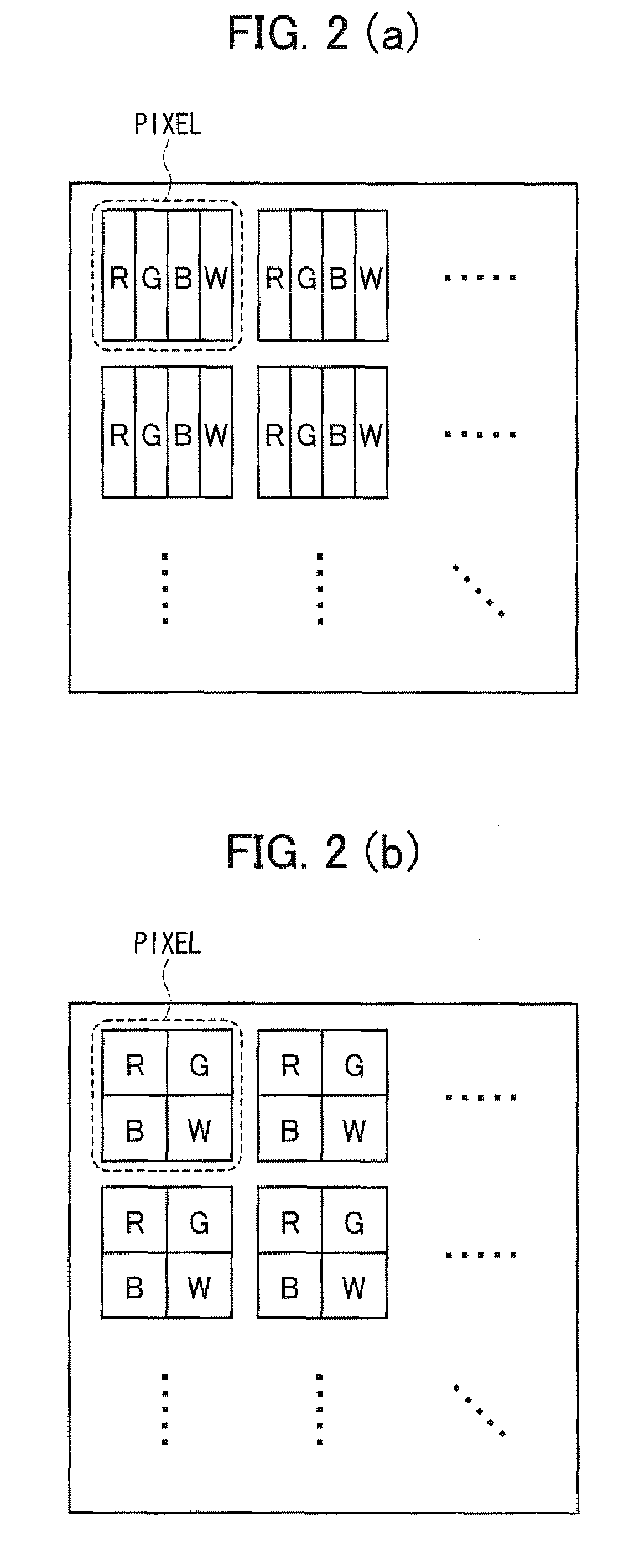
[0039]The liquid crystal panel 13 is arranged so that an N-number of pixels are disposed in a matrix manner, and each pixel is made up of four sub pixels as R (red), green (G), blue (B), and W (white) sub pixels as illustrated in FIG. 2(a) and FIG. 2(b). Note that, shapes and a positi...

embodiment 2

[0101]In Embodiment 1, the luminance Wi incorporated into the W sub pixel in the target pixel is max (Ri, Gi, Bi) / 2 in case where min (Ri, Gi, Bi)≧max (Ri, Gi, Bi) / 2. Further, in case where min (Ri, Gi, Bi)

Wi=min(max(Ri,Gi,Bi) / 2,min(Ri,Gi,Bi))

[0102]However, in Embodiment 1, the W sub pixel luminance Wi calculated by the foregoing expression is optimal strictly only in case where a white luminance property of the RGB sub pixels is equal to a white luminance property of the W sub pixel. Herein, the condition under which a white luminance property of the RGB sub pixels is equal to a white luminance property of the W sub pixel means a condition under which a display luminance P1 in case where a transmittance of each of the RGB sub pixels is x % and a transmittance of the W sub pixel is 0% is equal to a display...


PUM


Abstract

The transmission liquid crystal display device includes a liquid crystal panel and a backlight, wherein the liquid crystal panel has pixels each of which is divided into four sub pixels as red (R), green (G), blue (B), and white (W) sub pixels. Further, an emission luminance of the backlight can be controlled.

Description

[0001]This Nonprovisional application claims priority under 35 U.S.C. §119(a) on Patent Application No. 300845 / 2006 filed in Japan on Nov. 6, 2006 and Patent Application No. 008457 / 2007 filed in Japan on Jan. 17, 2007, the entire contents of which are hereby incorporated by reference.FIELD OF THE INVENTION[0002]The present invention relates to a transmission liquid crystal display device using an active backlight as a light source.BACKGROUND OF THE INVENTION[0003]There are various kinds of color displays, and these color displays are in practical use. Flat type displays are roughly categorized into a self-luminous display such as a PDP (plasma display panel) and a non-luminous display represented by an LCD (liquid crystal display device). As the LCD which is the non-luminous display, a transmission LCD having a backlight disposed on a rear side of a liquid crystal panel is known.[0004]FIG. 11 is a cross sectional view illustrating a general structure of the transmission LCD. The tra...

Claims


Application Information

Patent Timeline
Patent Type & Authority Patents(United States)
IPC IPC(8): G09G3/36
CPCG02F1/133514G09G3/3413G09G3/3607G02F2201/52G09G2300/0452G09G2320/0242G09G2320/0285G09G2320/0646G09G2330/023G09G2340/06G09G2360/16G02F1/133
Inventor AOKI, ATSUSHIMURAMATSU, TSUYOSHIMORISUE, TAKASHITANAKA, HIROSHIYUMOTO, MANABUEHIRO, MASAYUKI
Owner SHARP KK
Why Eureka
Try Eureka