Image display device and method of controlling same

a technology of image display and display luminance, which is applied in the direction of color television details, picture reproducers using projection devices, instruments, etc., can solve the problems of not showing the original color represented by the image signal, the difficulty of accurately adjusting the display position of the sub-pixels constituting one pixel, and the difficulty of preventing the coloring of the pixel. , to achieve the effect of reducing the display luminance of the sub-pixel

Active Publication Date: 2018-08-02
SEIKO EPSON CORP
View PDF2 Cites 3 Cited by
  • Summary
  • Abstract
  • Description
  • Claims
  • Application Information

AI Technical Summary

Benefits of technology

[0018]In another preferred aspect of the invention, the invention is implemented as a method of controlling an image display device having a plurality of light modulators corresponding respectively to color components, adapted to output light beams, which are modulated by image signals of a plurality of sub-pixels corresponding respectively to the color components and belonging to each of pixels constituting a display target image, by the respective light modulators, adapted to combine output light beams of the respective light modulators with each other, and adapted to display images formed of the respective color components on a display surface so as to overlap each other, the method including the steps of obtaining a position shift of a display position from a reference position in the display surface of the sub-pixel of the display target image, making the image display device perform a process of performing a pixel displacing correction adapted to shift a position of the sub-pixel in the display target image on the image signal of the sub-pixel supplied to at least one of the light modulators to thereby compensate position shifts of the display positions of the sub-pixels constituting the images of the respective color components to be displayed on the display surface with respect to a reference position, and making the image display device perform a boundary correction of decreasing luminance represented by the image signal of a sub-pixel of another color component of the pixel, to which the sub-pixel belongs, with respect to the sub-pixel, which moves outside an effective display range due to the pixel displacing correction.
[0019]According to this aspect of the invention, since the boundary correction of decreasing the luminance represented by the image signal of a sub-pixel of another color component of the pixel, to which the sub-pixel belongs, is performed with respect to the sub-pixel, which moves outside the effective display range to have display luminance one of equal to and lower than the predetermined value due to the pixel displacing correction, it is possible to prevent the coloring of the pixel from occurring due to the decrease in the display luminance of the sub-pixel caused of the pixel displacing correction.

Problems solved by technology

Here, if the number of pixels of a display image by the projector is increased, positioning of each of the sub-pixels by the optical system tends to become difficult.
However, it is difficult to accurately adjust all of the display positions of the sub-pixels constituting one pixel.
Therefore, there occurs a problem that the original color represented by the image signal is not displayed.
In this case, in the case in which sub-pixels of other color components belonging to the same pixel as the sub-pixel are located within the effective display range, and there is no decrease in display luminance, there is a problem that coloring occurs in the pixel.
As described above, in the case of providing the parting pixels in order to prevent the coloring, it is necessary to provide the light modulators with the element corresponding to the parting pixels, and there arises a problem that the light modulators grow in size accordingly.
Therefore, there arises a problem that a black frame corresponding to the parting pixels performing the black display is visually recognized depending on the contrast of the display target image.
Due to such circumstances, there also exist a lot of projectors not provided with the parting pixels.
However, when performing the pixel displacing correction in the projector not provided with the parting pixels, there arises a problem of coloring in the vicinity of the boundary of the effective display range described above. FIG. 16 shows a problem, which arises in the case of not providing the parting pixels Mi in the situation shown in FIG. 14 and FIG. 15.

Method used


Image

  • Image display device and method of controlling same
  • Image display device and method of controlling same
  • Image display device and method of controlling same

Examples


Embodiment Construction

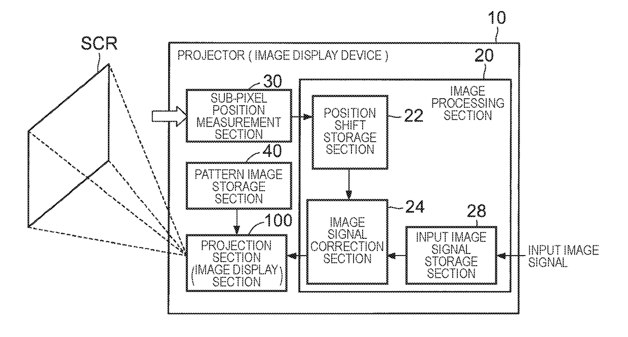
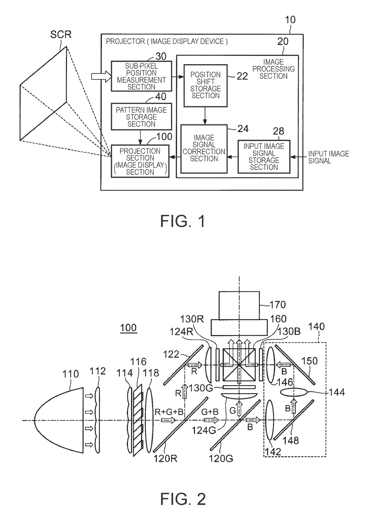
[0037]FIG. 1 is a block diagram showing a configuration example of a projector as an embodiment of an image display device according to the invention.

[0038]The projector 10 according to the present embodiment projects the light, which is modulated based on image signals of a plurality of sub-pixels constituting one pixel, on a screen SCR as a display surface to thereby perform image display. The projector 10 includes an image processing section 20, a pattern image storage section 40, a sub-pixel position measurement section 30, and a projection section 100 as an image display section.

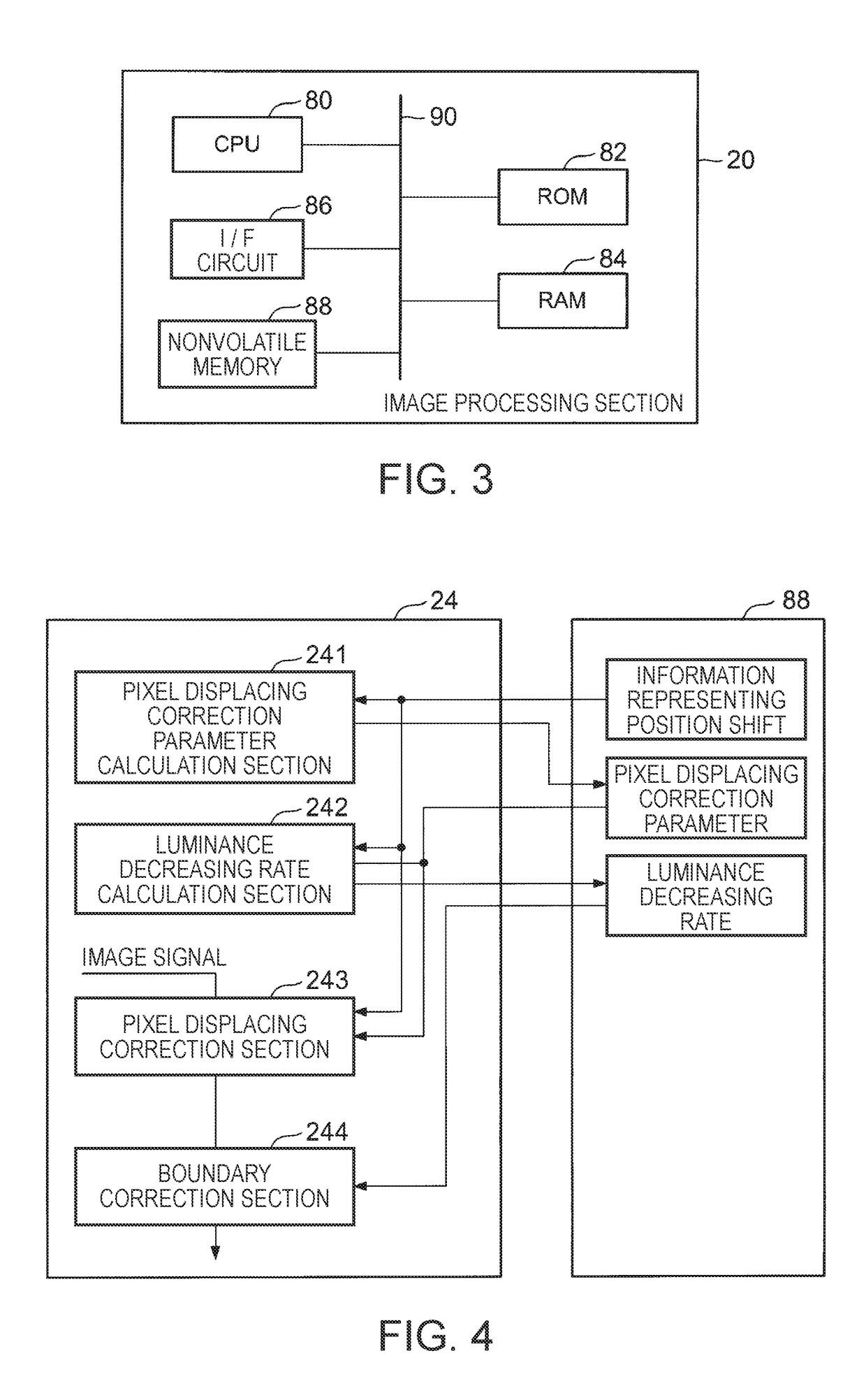
[0039]The image processing section 20 performs a correction process corresponding to the position shifts (or position shift vectors) of the display positions of the sub-pixels, which constitute each of the pixels of the image projected on the screen SCR, from reference positions to an input image signal for each of sub-pixels from an image signal generation device (not shown). The position shifts of the...


PUM


Abstract

A pixel displacing correction section performs a pixel displacing correction adapted to shift a position of the sub-pixel in the display target image on the image signal of the sub-pixel supplied to a plurality of light modulators to thereby compensate position shifts of the display positions of the sub-pixels constituting the images of the respective color components to be displayed on the display surface with respect to a reference position. A boundary correction section decreases the luminance represented by the image signal of the sub-pixel of another color component of the pixel, to which the sub-pixel belongs, with respect to the sub-pixel having completely moved outside the effective display range due to the pixel displacing correction.

Description

CROSS-REFERENCE[0001]The entire disclosure of Japanese Patent Application No. 2017-016573, filed Feb. 1, 2017 is expressly incorporated by reference herein.BACKGROUND1. Technical Field[0002]The present invention relates to an image display device such as a projector, and a method of controlling the image display device.2. Related Art[0003]The image display device such as a projector is provided with a light modulator such as a liquid crystal light valve or a mirror device for each of the color components of R (red), G (green), and B (blue) of a display target image. Further, image signals of sub-pixels of the respective color components of R, G, and B constituting a plurality of pixels in the display target image are provided to the light modulators corresponding respectively to the color components, and output light beams of the respective light modulators are combined with each other via an optical system to irradiate a display surface. In such a manner, the images of the respecti...

Claims


Application Information

Patent Timeline
Patent Type & Authority Applications(United States)
IPC IPC(8): H04N9/31
CPCH04N9/3182H04N9/3105H04N9/315G09G3/001H04N9/3194
Inventor KITAGAWA, TAKU
Owner SEIKO EPSON CORP
Why Eureka
Try Eureka