Apparatus, method, and system for roadway lighting using solid-state light sources

a technology of solid-state light sources and apparatuses, applied in the direction of condensers, instruments, lighting support devices, etc., can solve the problems of limiting the effectiveness of responding to changing driving conditions and limited in the selection of color properties

Active Publication Date: 2011-03-31
MUSCO
View PDF36 Cites 54 Cited by
  • Summary
  • Abstract
  • Description
  • Claims
  • Application Information

AI Technical Summary

Benefits of technology

[0011]The emergence of light emitting diodes (LEDs) and other solid-state devices as increasingly affordable light sources offers the potential for use in roadway lighting, particularly because a plurality of said light sources can be contained in a single fixture but controlled independently; this permits customization of light projected therefrom far beyond what is possible and / or cost-permissible using traditional light sources.
[0012]Envisioned are apparatus, methods, and systems whereby a plurality of solid-state light sources in a fixture may be aimed, collimated, or otherwise controlled so to suitably illuminate a roadway (or the like) while preserving driver visibility, and in a manner that provides benefits beyond merely increasing the number of light sources in a fixture. Beyond the benefit of increased aiming capabilities which, for example, allows light to be projected according to a complex beam pattern, some subset of the solid-state light sources could be of differing color properties so to aid in improving visibility during particular environmental conditions. Further, said light sources could be controlled remotely such that they can be selectively turned on, off, or dimmed, for example, according to need or preference. As is well known in the art, traditional light sources (e.g., HPS, MH, etc.) are somewhat limited in their selectable color properties and require significant time to reach maximum luminous output after being turned off, thereby limiting their effectiveness in responding to changing driving conditions.
[0016]b. apparatus and methods for minimizing glare and / or other adverse lighting effects commonly experienced by roadway drivers; and
[0018]One system according to aspects of the present invention comprises fixtures including a plurality of solid-state light sources, each of which may be of selectable optical properties, aiming, color, or the like. Said fixtures are elevated at or near driver eye height on a bridge or in a tunnel, for example, and are designed so to (i) illuminate the roadway, (ii) provide a reference point for drivers, and (iii) greatly reduce or eliminate glare for the typical driver. It is of note that described herein glare is defined as any perceived brightness which interferes with a driver's vision and is not limited to a type of glare (e.g., discomfort glare) or a direction of viewing (e.g., directly at the light source).

Problems solved by technology

As is well known in the art, traditional light sources (e.g., HPS, MH, etc.) are somewhat limited in their selectable color properties and require significant time to reach maximum luminous output after being turned off, thereby limiting their effectiveness in responding to changing driving conditions.

Method used


Image

  • Apparatus, method, and system for roadway lighting using solid-state light sources
  • Apparatus, method, and system for roadway lighting using solid-state light sources
  • Apparatus, method, and system for roadway lighting using solid-state light sources

Examples


embodiment i

B. Exemplary Method and Apparatus Embodiment I

[0041]A more specific exemplary embodiment, utilizing aspects of the generalized example described above, will now be described. The present embodiment utilizes concepts of adjusting how light is aimed in the horizontal plane; of course, this does not preclude adjusting light in the vertical plane as well.

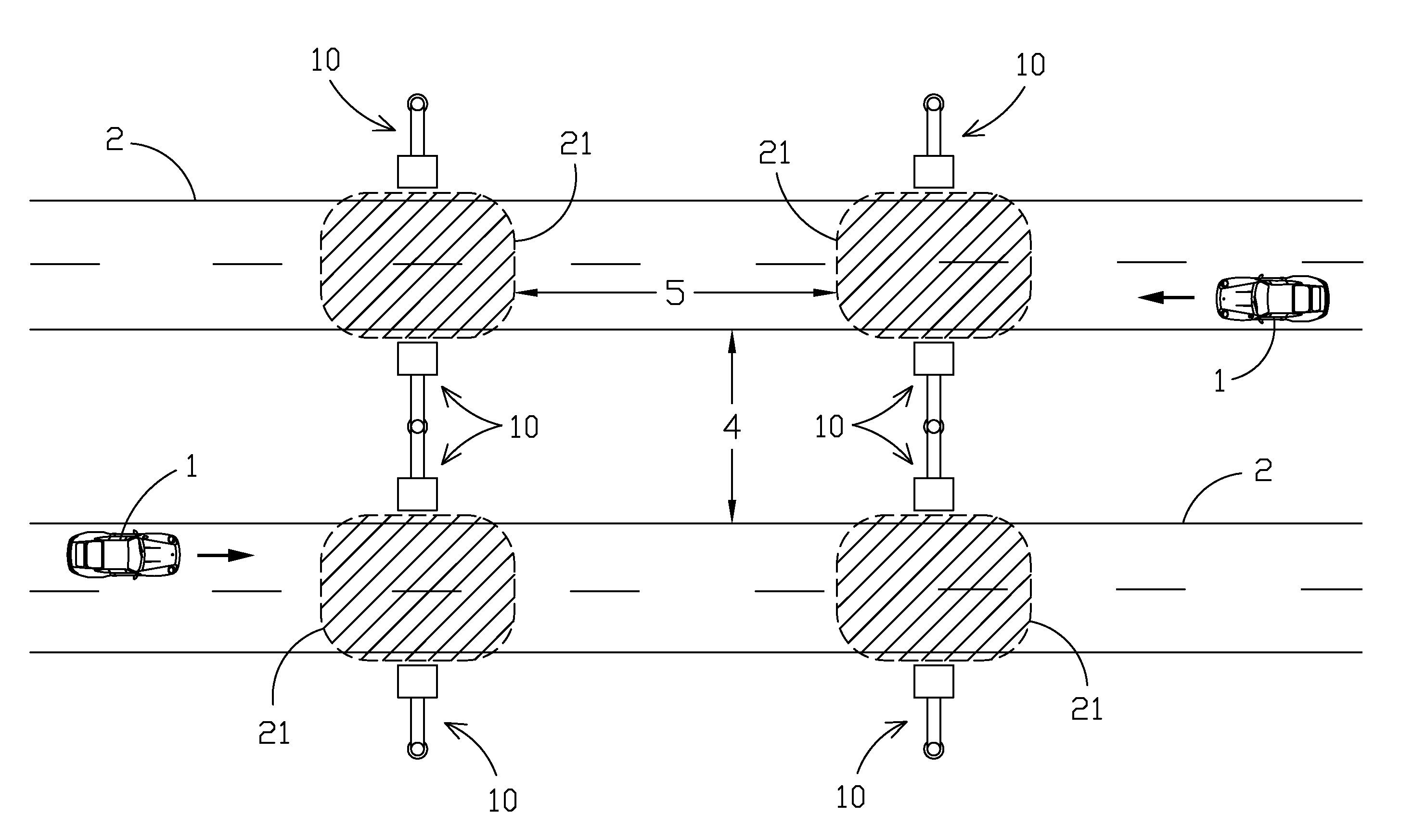
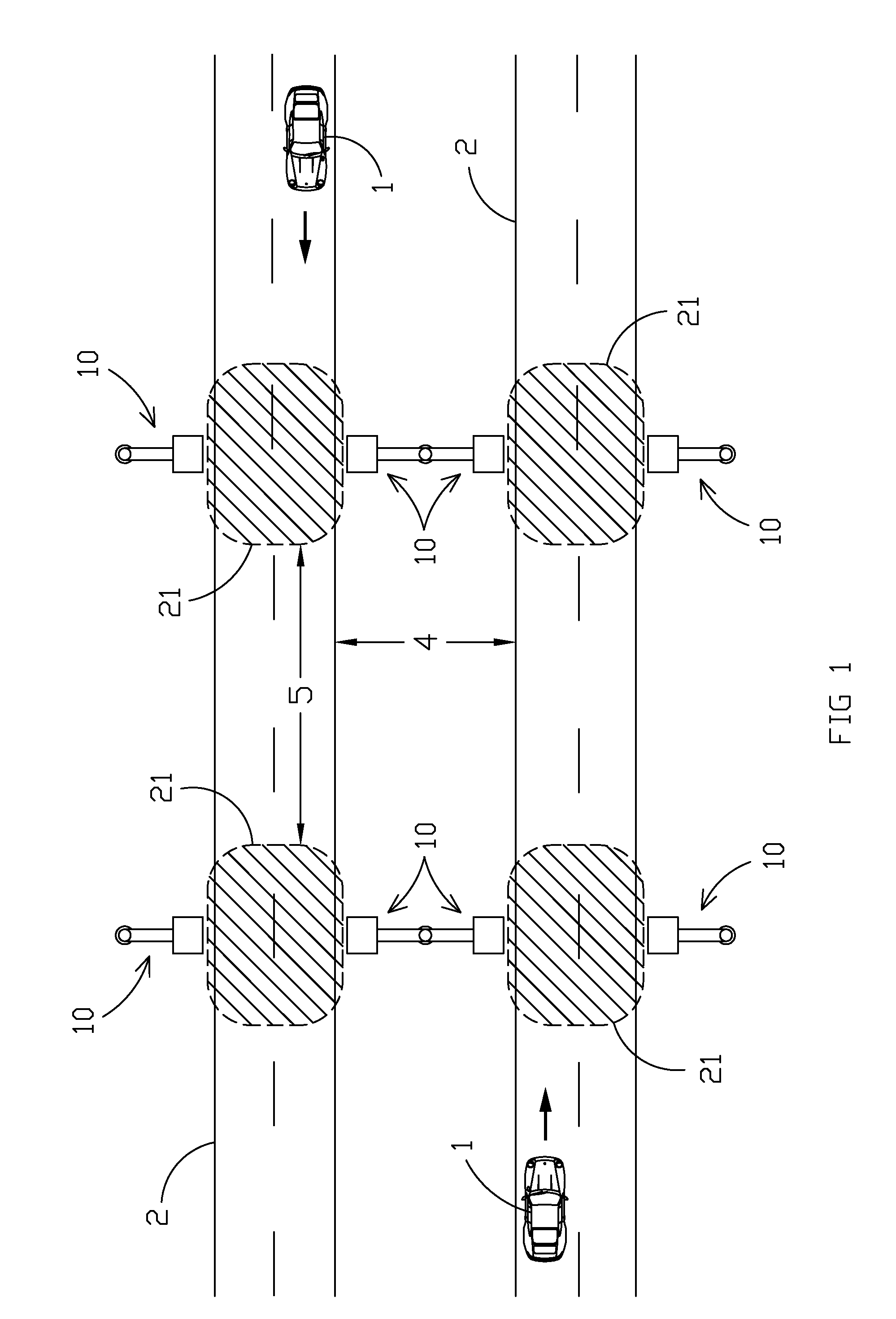
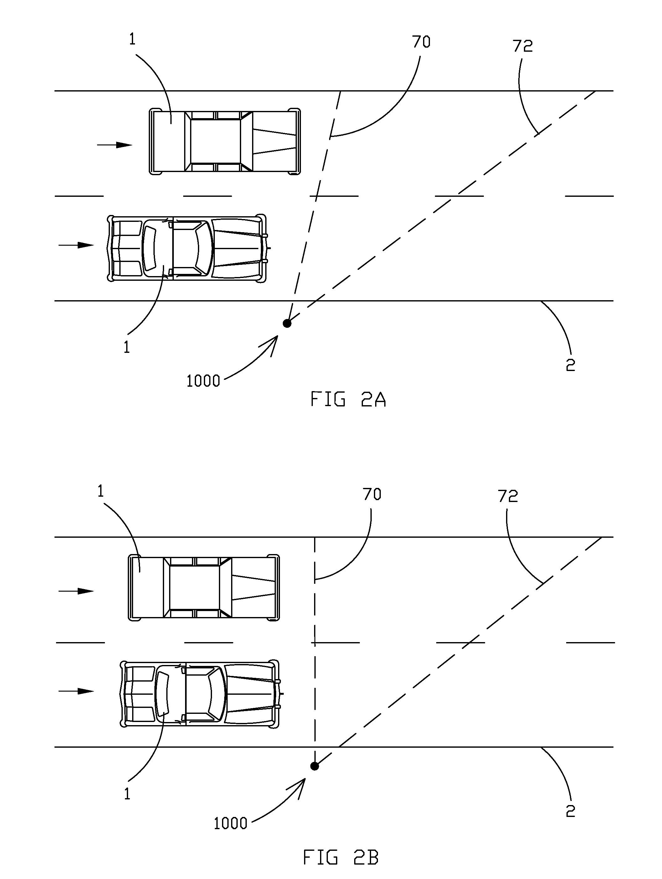
[0042]FIG. 4A illustrates the general roadway scenario previously described in which a vehicle 1 travels along a roadway 2; is of note that as illustrated travel in both lanes on either side of median 4 is in the same direction and indicated by arrows. As envisioned, fixtures 100 are aimed so to project light generally forward of vehicle 1 as previously described for fixtures 1000 (and illustrated in FIGS. 2A and B). The spacing between fixtures 100 approximates that of current roadway lighting fixtures (e.g., on the order of 60-80 meters), but because light is directed with traffic the mounting height is greatly reduced (e.g., reduced ...

embodiment 2

C. Exemplary Method and Apparatus Embodiment 2

[0050]An alternative embodiment envisions a roadway lighting system which utilizes concepts of adjusting how light is aimed in the vertical plane; of course, this does not preclude adjusting light in the horizontal plane as well.

[0051]FIG. 5A illustrates a general roadway scenario in which four lanes of traffic flow across a bridge, two lanes in each direction in accordance with vehicles 1 and arrows projecting therefrom. As envisioned, fixtures 200 are affixed to existing guardrails on the bridge, primarily to eliminate the cost of a support structure; this is achieved via a bracket 203 and support arm 207 (see FIGS. 5B-D). As designed, bolts 204 extend through aperture 205 in bracket 203 and aperture 206 in arm 207 and are secured by a nut or analogous component (not illustrated). Arm 207 is fixed to fixture 200 (e.g., by bolts 216 and / or other methods including but not limited to screws, rivets, welding, and adhesives). Aperture 206 i...


PUM

PropertyMeasurementUnit
heightaaaaaaaaaa
heightaaaaaaaaaa
angleaaaaaaaaaa

Abstract

Disclosed herein are apparatus, methods, and systems for illuminating roadways, paths, tunnels, bridges, and areas adjacent to such in a manner which minimizes glare and / or other adverse lighting effects commonly experienced by night-time drivers. According to aspects of the invention, horizontal and vertical aiming of a plurality of solid-state light sources permits projected light from a fixture to be tailored to roadway features (e.g., bends in the road) and in some cases, permits the mounting height of fixtures to be reduced which can make the envisioned system a cost-effective alternative to traditional roadway lighting.

Description

CROSS-REFERENCE TO RELATED APPLICATIONS[0001]This application claims priority under 35 U.S.C. §119(e) of provisional application Ser. Nos. 61 / 246,033 filed Sep. 25, 2009 and 61 / 254,945 filed Oct. 26, 2009, which applications are hereby incorporated by reference in their entireties.[0002]This application also claims benefit under 35 U.S.C. §120 to U.S. application Ser. No. 12 / 751,519, filed Mar. 31, 2010 which application is hereby incorporated by reference in its entirety.BACKGROUND OF THE INVENTION[0003]The present invention generally relates to the illumination of roadways at night. More specifically, the present invention relates to the use of solid-state light sources in roadway lighting as a way to improve over state of the art roadway lighting.[0004]The adequate illumination of roadways is known to be problematic, particularly because of the competing interests in designing roadway lighting systems. For example, one usually seeks to minimize the cost of a lighting system (both...

Claims


Application Information

Patent Timeline
Patent Type & Authority Applications(United States)
IPC IPC(8): H05B37/02F21S8/00H05K13/00
CPCF21S8/086Y02B20/72F21V23/0435F21W2131/103F21Y2101/02Y10T29/49002F21Y2105/001H05B37/02F21W2131/107F21V29/004F21V21/005F21V19/001F21V14/08F21V11/18F21S8/08F21S4/003F21S2/005F21K9/00G02B19/0066G02B19/0028F21Y2103/003F21V29/75F21V29/76F21V21/30F21V29/74F21S4/20F21Y2103/10F21Y2105/10F21Y2115/10H05B47/10F21V14/02
Inventor GORDIN, MYRON
Owner MUSCO
Why Eureka
Try Eureka