Viewing and display apparatus

a technology of viewing and display apparatus, applied in the field of astronomy, can solve the problems of inability to implement the norton system, inability to work with the device, and inability to solve the problem of introducing ambiguity that cannot be resolved, so as to minimize rotation error, eliminate the source of large error inherent, and accurate direction sensing

Inactive Publication Date: 2005-11-10
YAMCON
View PDF33 Cites 24 Cited by
  • Summary
  • Abstract
  • Description
  • Claims
  • Application Information

AI Technical Summary

Benefits of technology

[0005] The devices and methods described below provide critical enablement and improvements for the Norton device. One improvement provides for gimballing of the inclinometer of Norton, to eliminate a source of large error inherent in normal use of the device. Another improvement provides for gimballing of an inclinometer or gravitational sensor, and a hunting gravitational sensor, to provide accurate direction sensing. Another improvement provides for use of accelerometer based sensor disposed parallel to the viewing axis of the device to minimize rotation error. Other improvements provide rotation sensing and for rotation and scaling of superimposed images to account for user rotation of the device and user-created variation in the field of view presented by the device to the eye.

Problems solved by technology

Though Norton was described in the context of a hand-held star-gazing device, and purported to provide information about asterisms (constellations or groups of stars) in the field of view, the device does not work unless held with certain components held perfectly vertical during use.
Any twisting or rotation of the device about the viewing axis necessarily causes errors, and introduces ambiguity that cannot be resolved.
Thus, it is not possible to implement the Norton system, as proposed by Norton, in a hand-held device.
The Norton system suffers from crippling defects.
Without perfect vertical alignment of the inclinometer the device cannot unambiguously determine its orientation.
If the device is not held perfectly vertically, that is, if it is twisted or rotated about the viewing axis, projection errors are introduced into the output from the inclinometer, so that the device has inadequate information regarding its inclination.
In the case that the twist induced error is small enough that the device can determine its viewing axis with enough precision to generate a reference display that corresponds to constellations in the field of view, the device has no way to determine that it is twisted, and thus cannot rotate the reference display to align with the constellation.
The Norton system has a further limitation in regards to the viewing system employed.
There is an inherent problem with this approach, it does not allow for any deviation in the distance that the operator is holding the device between their eye and the device.
This is a problem with no disclosed or obvious solution proposed by Norton.

Method used


Image

  • Viewing and display apparatus
  • Viewing and display apparatus
  • Viewing and display apparatus

Examples


Embodiment Construction

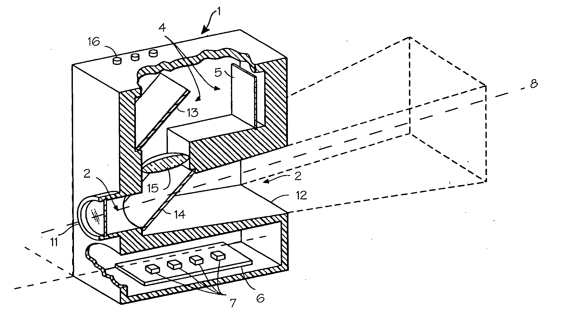
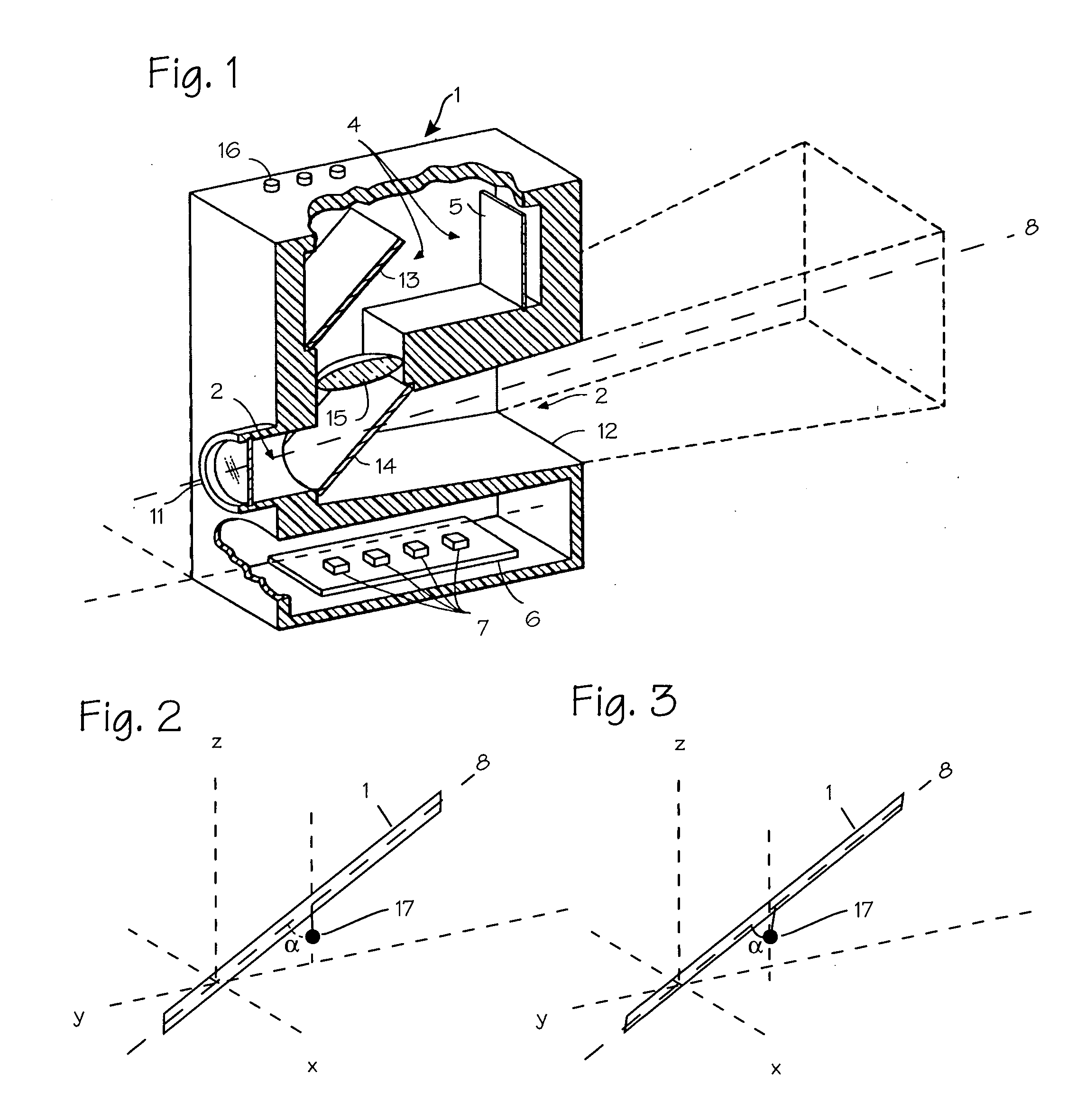
[0012]FIG. 1 illustrates the device proposed in Norton. The device includes the housing 1, an optical arrangement, indicated generally at 2, for defining the field of view 3 of the apparatus, an overlay arrangement 4, for overlaying or superimposing a reference display on that field of view, and LCD display 5 on which the reference display is generated, a printed circuit board 6, which includes the system electronics and a sensing mechanism, indicated diagrammatically at 7, for sensing the three-dimensional direction in which field of view 3 is aimed. The field of view is centered around the viewing axis 8. The “optical arrangement” comprises a view port 11 and a field stop 12 and other optics to force the reference display to appear at infinity. The overlay arrangement 4 comprises the LCD display 5, a re-directing mirror 13, an image combining mirror 14, and a focusing lens 15. Norton provides the lens 15 to modify the reference display presented to the user so that it appears at i...


PUM


Abstract

A celestial object location and identification device.

Description

FIELD OF THE INVENTIONS [0001] The inventions described below relate the field of astronomy, specifically to an electronic device capable of locating and identifying celestial objects. BACKGROUND OF THE INVENTIONS [0002] Norton, Viewing And Display Apparatus, U.S. Pat. No. 5,311,203 (May 10, 1994) describes a viewing device for identifying features of interest which appear in the field of view of the device. Though Norton was described in the context of a hand-held star-gazing device, and purported to provide information about asterisms (constellations or groups of stars) in the field of view, the device does not work unless held with certain components held perfectly vertical during use. Any twisting or rotation of the device about the viewing axis necessarily causes errors, and introduces ambiguity that cannot be resolved. Thus, it is not possible to implement the Norton system, as proposed by Norton, in a hand-held device. Norton consists of a box-like housing with a viewing chan...

Claims


Application Information

Patent Timeline
Patent Type & Authority Applications(United States)
IPC IPC(8): A63B69/16G09B23/00G09B23/06G09B27/00G09B27/04G09B29/00G09B29/10
CPCG09B23/06G09B29/106G09B29/007G09B27/04
Inventor LEMP, MICHAEL IIIHATALSKI, MICHAEL
Owner YAMCON
Why Eureka
Try Eureka