Safety module electrical distribution system

a safety module and electrical distribution system technology, applied in the direction of coupling contact member, connection contact member material, coupling device connection, etc., can solve the problems of cost, safety and functionality, and the installation of wall panels of standard ac electrical systems, so as to eliminate the shock exposure of other workers, eliminate the effect of cutting and patching repairs, and easy and safe replacement of broken sockets and switches

Inactive Publication Date: 2005-11-10
BAUM FAMILY TRUST DTD 1 11 2001 +143
View PDF36 Cites 27 Cited by
  • Summary
  • Abstract
  • Description
  • Claims
  • Application Information

AI Technical Summary

Benefits of technology

[0007] A safety module electrical distribution system benefits the electrical contractor in several respects. A wiring module is installed internally to an electrical box and associated functional modules are removably installed into the wiring module without exposure to or access to electrical system wiring attached behind the panel. The journeyman's work can completed at the rough phase, when installation of the wiring module is complete. Thus, there is no need for the journeyman to return to the job site during the makeup phase because any semi-skilled laborer can insert, for example, an appropriate outlet or switch module. Further, there is no wiring access after the rough phase, protecting wiring integrity. Also, there are no exposed conductors or parts inside the electrical box that can be inadvertently damaged during wall panel installation.
[0008] The safety module electrical distribution system also benefits the general contractor. Because wiring is completed during rough framing, verification and activation of the building electrical system can be performed at the rough phase. Miswiring can be corrected before wall panels are installed and painted, eliminating cut and patch repairs. Early electrical system activation eliminates the need to use generators. Lack of third party access to the journeyman's wiring preserves integrity after verification and eliminates shock exposure to other workers.
[0009] The safety module electrical distribution system also benefits the homeowner. Replacement of broken sockets and switches can be easily and safely accomplished. Safety is enhanced by reducing exposure to electrical wiring and encouraging replacement of defective outlets and switches. Further, maintenance costs are reduced by reducing the need to hire an electrician for repairs. Wiring integrity is insured by reducing the opportunity of unqualified third parties to access the electrical system.

Problems solved by technology

Standard AC electrical systems are problematic in construction and use, with respect to costs, safety and functionality.
Also, during the makeup phase, installation of the wall panels can damage the work completed during the rough phase.
Another form of damage occurs when drywall compound or paint fouls the exposed cables, insulation and labeling.
From a general contractor's perspective, verification of the electrical contractor's work is not possible until after the makeup phase.
After the makeup phase, however, miswiring typically requires cutouts in the installed wall panels and associated patches after corrections are completed.
Further, the electrical system cannot be activated until after verification.
Thus, during the rough and makeup phases, electricity for tools and lighting must be supplied by generators, which create hazards due to fumes, fuel, and noise and are an unreliable electrical source.
In addition, until the trim phase is completed, unskilled personnel have access to the electrical cable.
Tampering can compromise the integrity of the electrical wiring and also create a safety problem after power is activated.
From a homeowner's perspective, there are problems with repair of the standard electrical wiring.
This exposure creates a shock hazard.
Further, a homeowner's reluctance to change out broken devices or to spend the money to hire an electrician also creates a shock and a fire hazard from continued use of cracked, broken or excessively worn outlets or switches.
In addition, the integrity of the original wiring becomes questionable if a homeowner or other third party removes and replaces an electrical device.
Miswiring by a third party can violate building codes and create shock and fire hazards, such as inadvertently switching the hot and neutral conductors, failing to attach ground wires, kinking or nicking conductors or improperly tightening connections.

Method used


Image

  • Safety module electrical distribution system
  • Safety module electrical distribution system
  • Safety module electrical distribution system

Examples


Embodiment Construction

System Overview

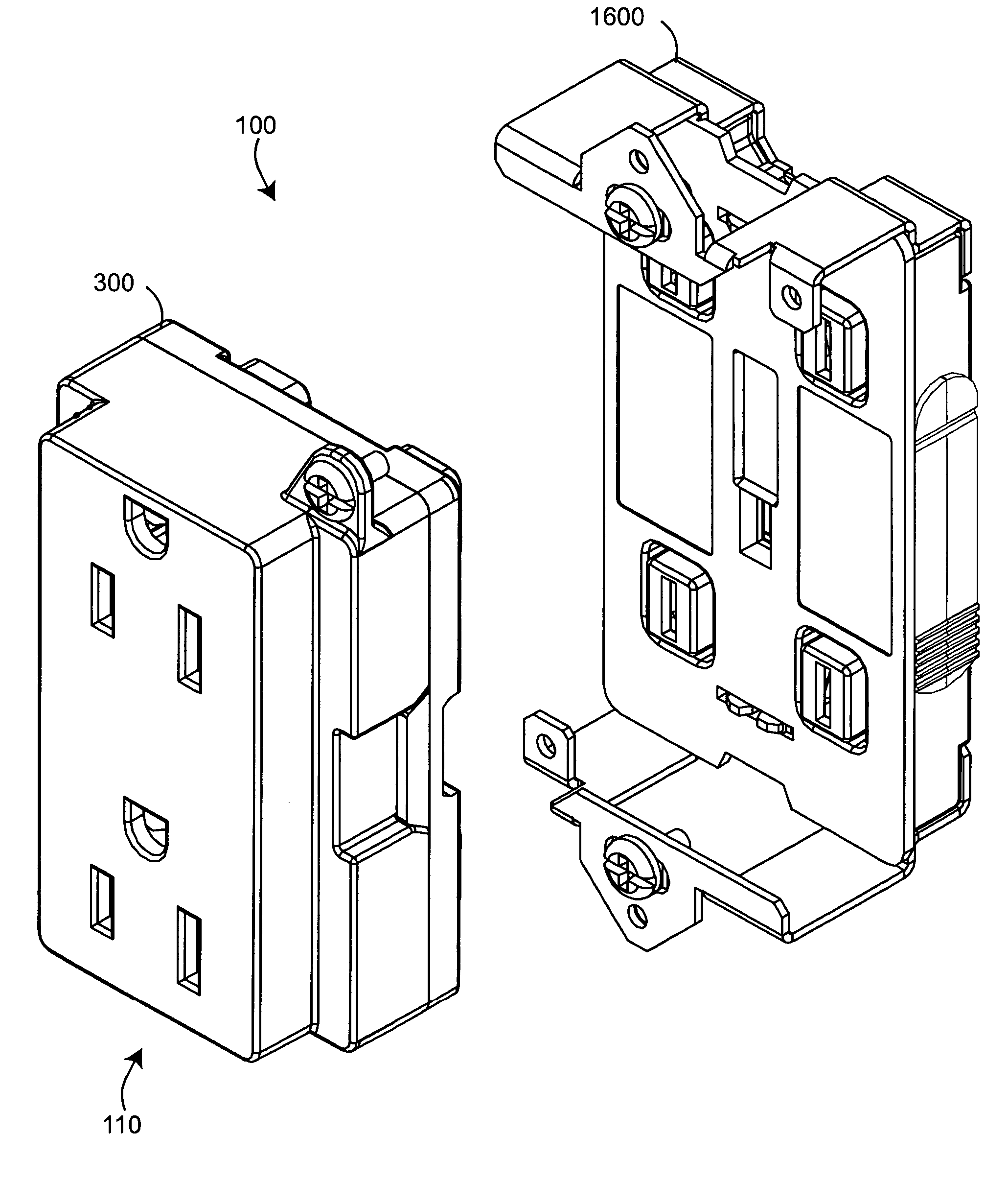
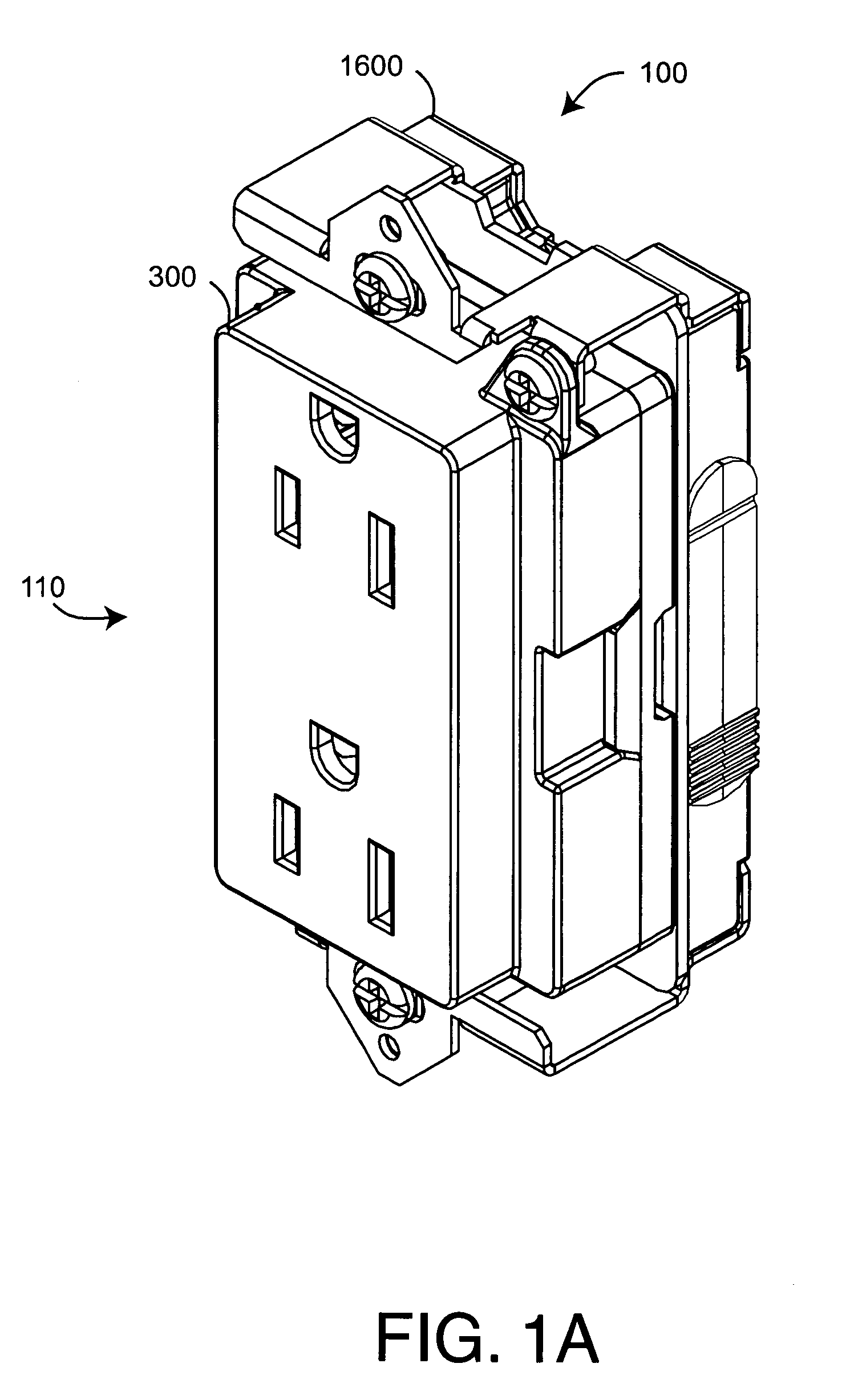
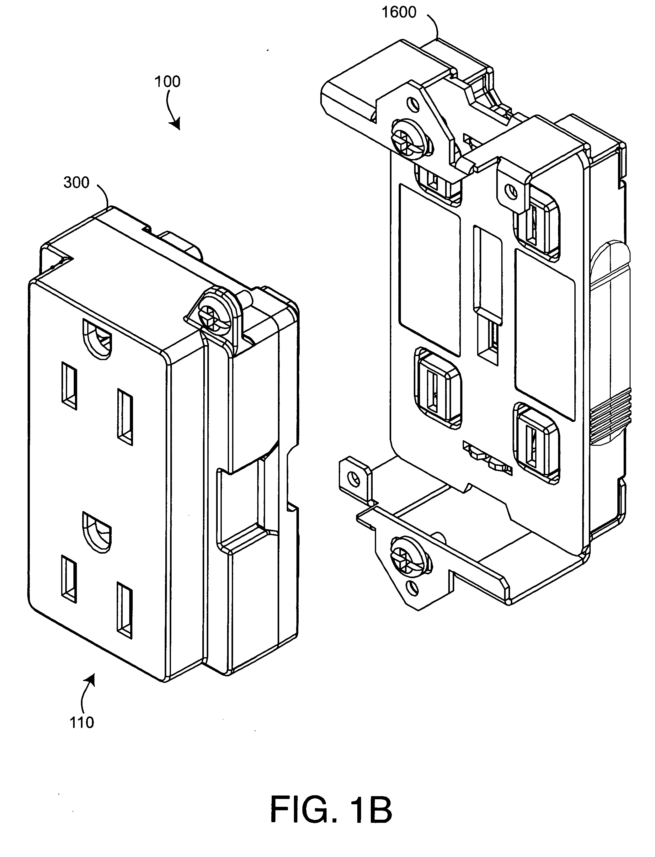
[0049]FIGS. 1-2 illustrate a safety module electrical distribution system 100 having a functional module 110 and a wiring module 1600. The electrical distribution system 100 is configured to mount within a standard electrical box (not shown), such as is typically installed within a building wall. In particular, the wiring module 1600 is configured to be easily installed within an electrical box, and a functional module 110 is configured to be removably plugged into the wiring module 1600, as described below. FIGS. 1A-B show an outlet module 300 in an installed and a removed position, respectively. FIGS. 2A-B show a switch module 900 in an installed and a removed position, respectively. A face plate (not shown) may be installed over a functional module 110 so as to provide an aesthetic trim.

[0050] As shown in FIGS. 1-2, each functional module 110 provides a user-accessible electrical distribution function. As shown in FIGS. 1A-B, the functional module 110 may be an ...


PUM

PropertyMeasurementUnit
electrical distributionaaaaaaaaaa
electrical poweraaaaaaaaaa
electricalaaaaaaaaaa

Abstract

An electrical distribution system comprises a wiring module and a functional module. The wiring module mounts within an electrical box and has a functional side and a wiring side. The functional module has a front side and a back side and removably installs in the wiring module functional side. A key extends from, and is positioned on, the back side so as to identify a type of functional module. An aperture is positioned on the wiring module functional side so as to accept the key only when the functional module is properly oriented with respect to the wiring module. The wiring module is mounted within the electrical box according to the functional module type.

Description

CROSS-REFERENCE TO RELATED APPLICATIONS [0001] This application is a divisional of U.S. patent application Ser. No. 10 / 443,444 entitled Safety Module Electrical Distribution System, filed May 22, 2003, which relates to and claims the benefit of prior U.S. Provisional Applications No. 60 / 383,269 entitled Safety Plug-In Module Electrical Distribution System, filed May 23, 2002, and No. 60 / 441,852 entitled Safety Module Electrical Distribution System, filed Jan. 21, 2003. All of the aforementioned prior applications incorporated by reference herein.BACKGROUND OF THE INVENTION [0002] Standard AC electrical systems are comprised of an electrical box and an electrical device, such as an outlet or switch, installed within the box. During a roughing phase of construction, electrical boxes are mounted to wall studs at predetermined locations. After the boxes are installed, a journeyman electrician routes power cables through building framing to the appropriate boxes. The power cable is fed t...

Claims


Application Information

Patent Timeline
Patent Type & Authority Applications(United States)
IPC IPC(8): H01H9/08H01H15/00H01R4/30H01R4/44H01R4/48H01R4/66H01R9/24H01R13/05H01R13/115H01R13/424H01R13/44H01R13/447H01R13/46H01R13/506H01R13/512H01R13/514H01R13/52H01R13/60H01R13/639H01R13/652H01R13/66H01R13/70H01R25/00H01R29/00H01R31/06H02J1/00
CPCH01H9/08Y10T29/49176H01H15/00H01H15/10H01R4/30H01R4/44H01R4/4818H01R4/66H01R9/24H01R9/2433H01R13/055H01R13/115H01R13/424H01R13/44H01R13/447H01R13/465H01R13/506H01R13/512H01R13/514H01R13/5213H01R13/6395H01R13/652H01R13/6658H01R13/701H01R24/22H01R24/78H01R25/006H01R29/00H01R31/06H01R2103/00H02G3/086H05B39/08Y10T29/49174Y10T29/49208Y10T29/49185Y10T29/49181H01H11/0006H01R4/48185H01R13/70H01R31/065
Inventor GORMAN, MICHAEL P.
Owner BAUM FAMILY TRUST DTD 1 11 2001
Why Eureka
Try Eureka