Electrical wiring method

a technology of electrical wiring and wires, applied in the direction of contact member manufacturing, connection contact member material, coupling device connection, etc., can solve the problems of electrical wiring construction, unnecessary installation costs, and installation of wall panels, so as to eliminate the shock exposure of other workers, replace the socket and switch easily and safely, and eliminate the effect of cutting and patching repairs

Inactive Publication Date: 2008-05-06
BAUM FAMILY TRUST DTD 1 11 2001 +143
View PDF23 Cites 100 Cited by
  • Summary
  • Abstract
  • Description
  • Claims
  • Application Information

AI Technical Summary

Benefits of technology

[0009]The safety electrical outlet and switch system benefits the electrical contractor in several respects. An aspect of the system is an electrical box, a wiring panel installed internally to the box and associated outlet and switch modules which snap into and out of the panel without exposure to or access to electrical system wiring attached behind the panel. The journeyman's work is completed at the rough phase, when installation of the wiring panel is complete. Thus, there is no need for the journeyman to return to the job site during the makeup phase because any semi-skilled laborer, following a punch-out code or other indicator on the panel, can snap-in an appropriate outlet or switch module. Further, there is no wiring access after the rough phase, protecting wiring integrity. Also, there are no exposed conductors or parts inside the electrical box that can be inadvertently damaged during wall panel installation. A protective cover is provided that prevents fouling by drywall compound or other materials during the makeup phase.
[0010]The safety electrical outlet and switch system also benefits the general contractor. Because wiring is completed during rough framing, verification and activation of the building electrical system can be performed at the rough phase. Miswiring can be corrected before wall panels are installed and painted, eliminating cut and patch repairs. Early electrical system activation eliminates the need to use generators. Lack of third party access to the journeyman's wiring preserves integrity after verification and eliminates shock exposure to other workers.
[0011]The system also benefits the homeowner. Replacement of broken sockets and switches can be easily and safely accomplished. Safety is enhanced by reducing exposure to electrical wiring and encouraging replacement of defective outlets and switches. Further, maintenance costs are reduced by reducing the need to hire an electrician for repairs. Wiring integrity is insured by reducing the opportunity of unqualified third parties to access the electrical system.

Problems solved by technology

Problems with Standard Wiring Construction
There are multiple problems with standard electrical wiring construction.
From the electrical contractor perspective, there are unnecessary costs associated with installation.
During the makeup phase, installation of the wall panels can damage the work completed during the rough phase.
One way in which damage occurs is router contact with exposed cables when drywallers create a hole to accommodate electrical box openings.
Another form of damage occurs when drywall compound or paint fouls the exposed cables, insulation and labeling.
From the general contractor perspective, there are other problems with the standard electrical wiring construction.
Verification of the electrical contractor's work is not possible until after the makeup phase.
After the makeup phase, however, miswiring typically requires cutouts in the installed wall panels and associated patches after corrections are completed.
Further, the electrical system cannot be activated until after verification.
Thus, during the rough and makeup phases, electricity for tools and lighting must be supplied by generators, which create hazards due to fumes, fuel, and noise and are an unreliable electrical source.
In addition, until the trim phase is completed, unskilled personnel have access to the electrical cable.
Tampering can comprise the integrity of the electrical wiring and also create a safety problem after power is activated.

Method used


Image

  • Electrical wiring method
  • Electrical wiring method
  • Electrical wiring method

Examples


Embodiment Construction

System Overview

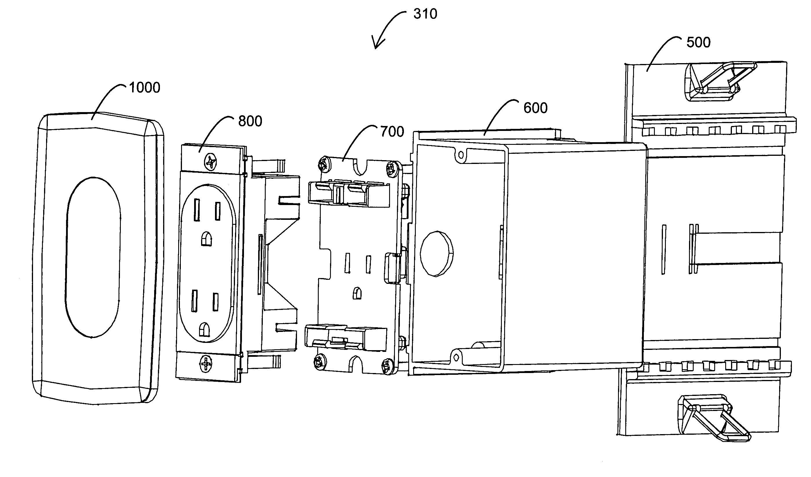
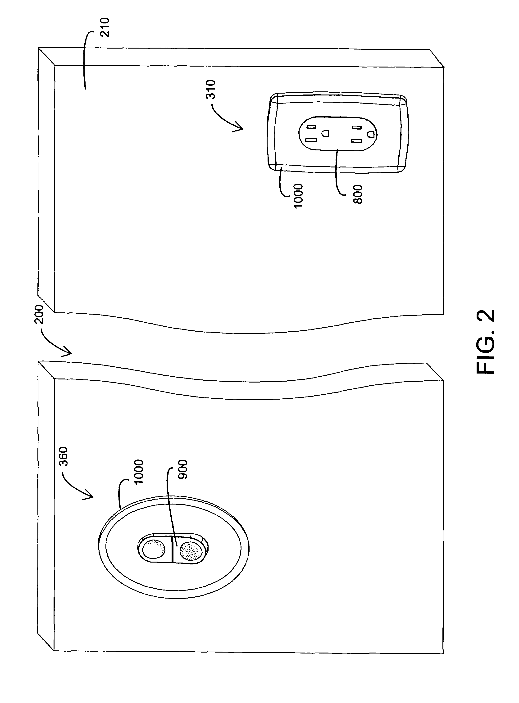
[0053]FIG. 2 illustrates one embodiment of an installed safety electrical outlet and switch system 200. As shown in FIG. 2, the outlet and switch system 200 comprises a outlet assembly 310 and a switch assembly 360. Each of these assemblies 310, 360 provide a user-accessible electrical function. The outlet assembly 310 is mounted in a wall 210 and functions to supply a user with electrical power through a conventional AC plug inserted into an outlet module 800. The switch assembly 360 is also mounted in the wall 210 and functions to allow a user to control electrical power to an outlet, a light or any of various electrical devices (not shown) by actuating a switch module 900. The installed outlet assembly 310 includes a face plate 1000 and an outlet module 800 mounted so that its visible portion is generally flush with the face plate 1000. The installed switch assembly 360 includes a face plate 1000 and a switch module 900 mounted so that its visible portion is in a p...


PUM

PropertyMeasurementUnit
distancesaaaaaaaaaa
distancesaaaaaaaaaa
specific distancesaaaaaaaaaa

Abstract

An electrical box is mounted on a wall stud, and a wiring panel is installed within the electrical box so as to partition the interior of the electrical box into a user inaccessible wiring compartment and a user accessible module compartment. A protective cover is attached to the wiring panel so as to protect the wiring panel during a makeup phase of wall panel installation and painting. After the makeup phase, the protective cover is removed from the wiring panel and a module having a user operable electrical function is mounted to the wiring panel within the user accessible module compartment.

Description

CROSS-REFERENCE TO RELATED APPLICATIONS[0001]This application is a continuation of U.S. patent application Ser. No. 10 / 685,294 filed Oct. 14, 2003 now abandoned, which is a continuation of U.S. patent application Ser. No. 10 / 023,393 filed Dec. 17, 2001, now abandoned, which is a divisional of U.S. patent application Ser. No. 09 / 553,425 filed Apr. 19, 2000, now U.S. Pat. No. 6,341,981 which relates to and claims the benefit of U.S. Provisional Patent Application No. 60 / 174,521 entitled Safety Electrical Wiring Assembly, filed Jan. 5, 2000. All of the above-referenced patent applications and patents are incorporated by reference herein.BACKGROUND OF THE INVENTION[0002]Installation of a standard AC electrical system in a new residence or commercial site occurs in three phases, corresponding to the building construction. The rough phase corresponds to rough framing of the building, prior to attachment of wall panels to the frame. During this phase, blue boxes or similar electrical boxes...

Claims


Application Information

Patent Timeline
Patent Type & Authority Patents(United States)
IPC IPC(8): H01R43/00H05K13/00H01R13/60H01R13/70H01R25/00H02B1/01H02G3/00H02G3/08
CPCH01R13/652H01R24/78H01R25/006H02G3/126H02G3/14H01R4/64H01R43/00Y10T29/49208H01R2103/00Y10T29/49169Y10T29/49194Y10T29/49126Y10T29/49128Y10T29/49174Y10T29/49204Y10T29/49222H01R13/70
Inventor GORMAN, MICHAEL
Owner BAUM FAMILY TRUST DTD 1 11 2001
Why Eureka
Try Eureka