Floor cleaning machine, particularly for industrial applications

a floor cleaning machine and industrial technology, applied in the direction of floor cleaning machines, vacuum cleaners, carpet cleaners, etc., can solve the problem that machines are not capable of ensuring optimum floor drying

Inactive Publication Date: 2005-11-17
COMAC SPA
View PDF5 Cites 20 Cited by
  • Summary
  • Abstract
  • Description
  • Claims
  • Application Information

AI Technical Summary

Benefits of technology

[0004] The aim of the present invention is to solve the problem noted above by providing a floor cleaning machine, particularly for industrial applications, that can perform deep cleaning of the floor so as to avoid, if the machine turns, leaving residues of dirty liquid on the floor, without having to use bulky floor wipers or powerful suction systems.

Problems solved by technology

A drawback that is observed in this type of machine arises from the fact that unless a wiper is provided that has a considerable width with respect to the width of the box-like structure of the machine and a powerful suction system connected to the suction intake, these machines are not capable of ensuring optimum floor drying if a turn is made as the machine travels.

Method used


Image

  • Floor cleaning machine, particularly for industrial applications
  • Floor cleaning machine, particularly for industrial applications
  • Floor cleaning machine, particularly for industrial applications

Examples


Embodiment Construction

[0012] In the examples of embodiments that follow, individual characteristics, given in relation to specific examples, may actually be interchanged with other different characteristics that exist in other examples of embodiments.

[0013] Moreover, it is to be noted that anything found to be already known during the patenting process is understood not to be claimed and to be the subject of a disclaimer.

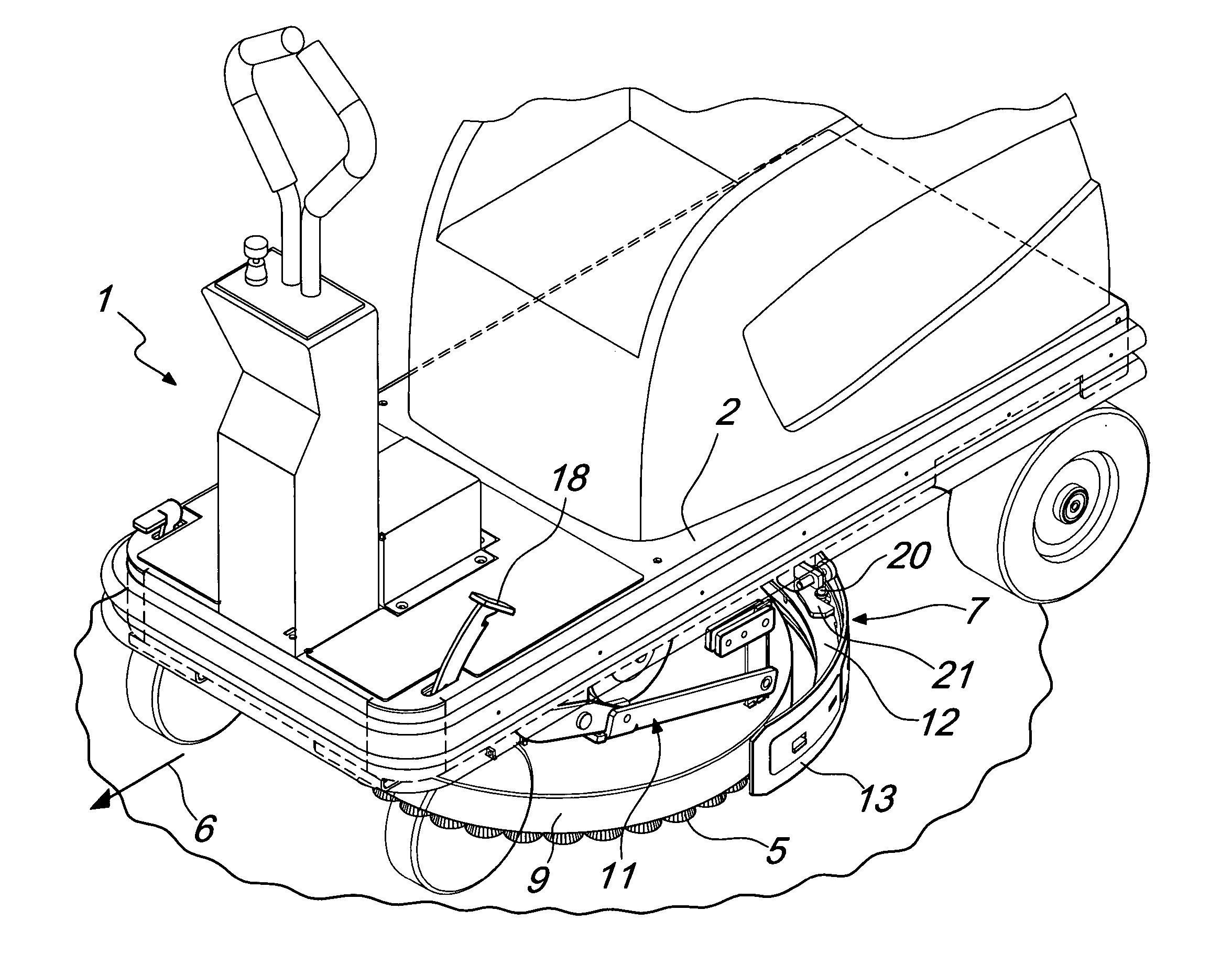
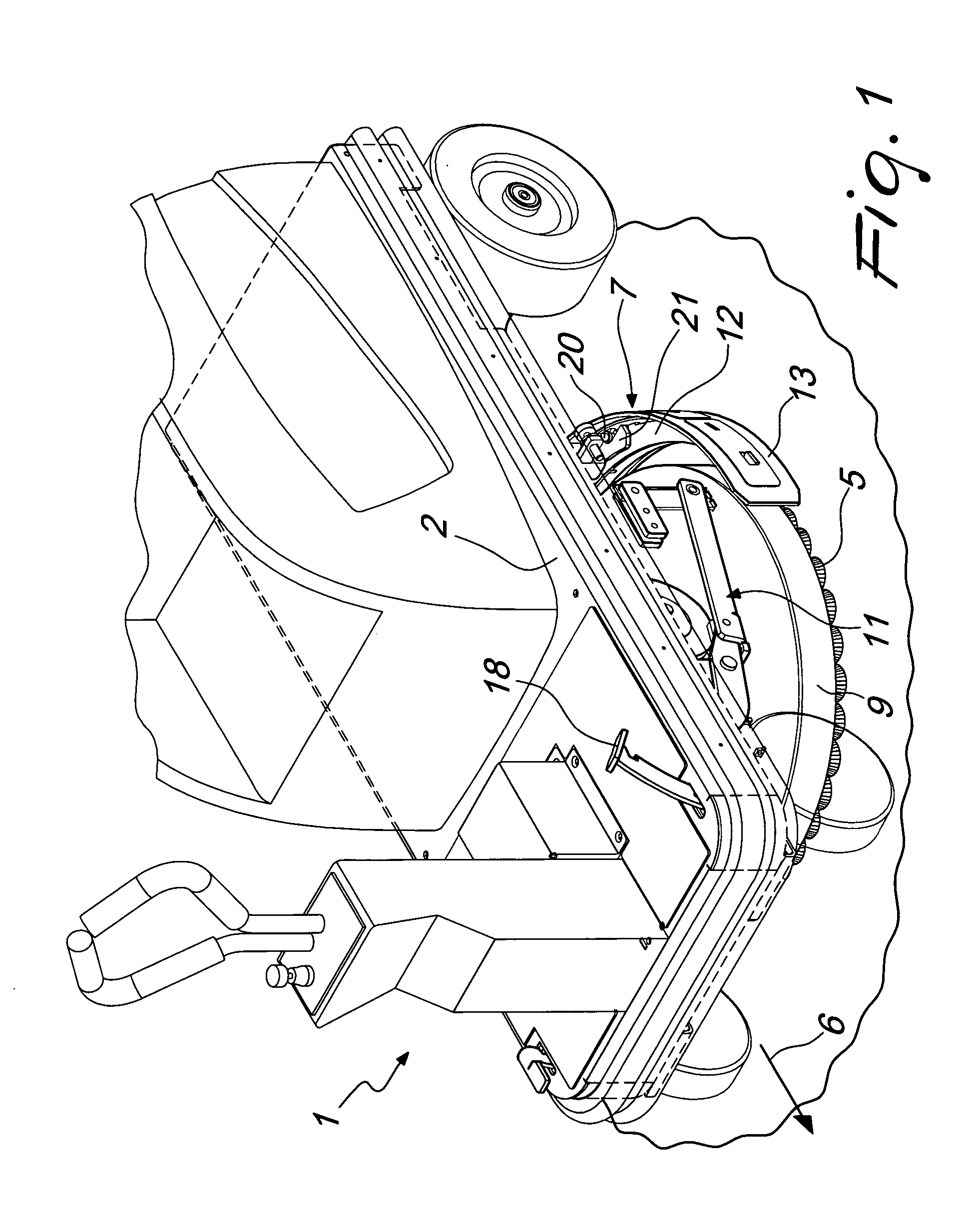
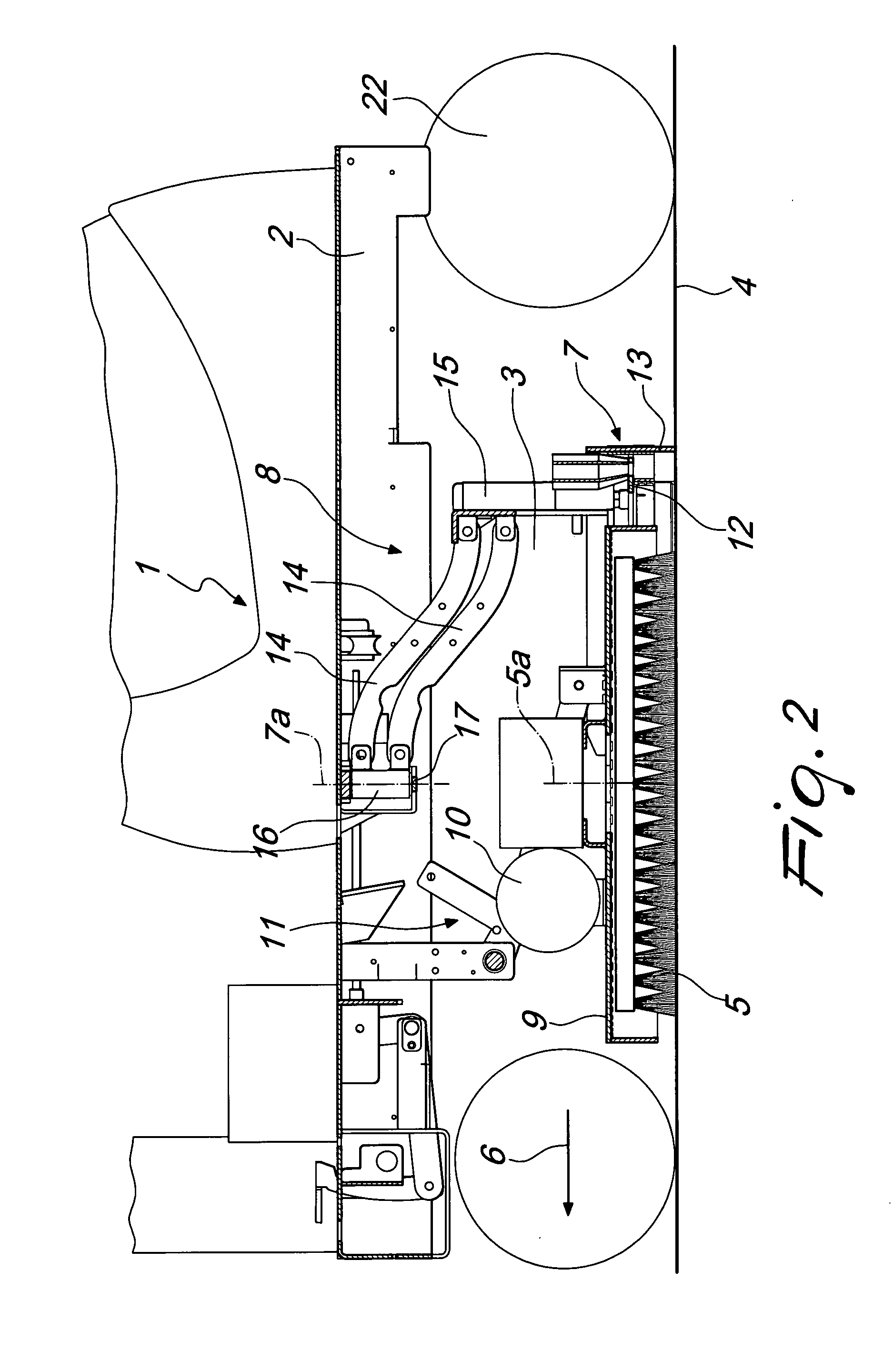
[0014] With reference to the figures, the floor cleaning machine particularly for industrial applications according to the invention, generally designated by the reference numeral 1, comprises a chassis 2, which supports in an upward region several service devices of the machine, such as for example means for dispensing the washing liquid, means for aspirating the washing liquid, and means for the electrical and / or mechanical actuation of said machine, all of which are of a per se known type and are not illustrated for the sake of simplicity.

[0015] As clearly shown, the chassis 2 may ...


PUM


Abstract

A floor cleaning machine, particularly for industrial applications, comprising a chassis that supports in a downward region at least one brush, which can be actuated with a rotary motion, and at least one floor wiper, which is arranged to the rear of the brush along the travel direction of the machine and is arranged substantially transversely to the travel direction of the machine, the floor wiper being freely rotatably associated with the chassis about a substantially vertical oscillation axis.

Description

[0001] The present invention relates to a floor cleaning machine, particularly for industrial applications. BACKGROUND OF THE INVENTION [0002] Floor cleaning machines are known which generally comprise a box-like structure that forms, in a downward region, a chamber that is open toward the floor and accommodates a nozzle for dispensing a washing liquid and a rotating brush that performs a mechanical action for deep cleaning of the floor. To the rear of the brush along the direction of travel of the machine, there is usually a floor wiper, substantially constituted by a strip or blade made of rubber, which is pressed elastically against the floor and is arranged substantially transversely to the direction of travel of the machine. The wiper is designed to collect the washing liquid and the dirt removed from the floor by the action of the brush so that they can be recovered by an appropriate suction intake, thereby leaving the floor clean and dry. [0003] A drawback that is observed in...

Claims


Application Information

Patent Timeline
Patent Type & Authority Applications(United States)
IPC IPC(8): A47L5/30A47L7/00A47L9/04A47L9/06A47L11/16A47L11/30
CPCA47L11/305A47L11/4038A47L11/4061A47L11/4052A47L11/4044
Inventor RUFFO, MASSIMILIANO
Owner COMAC SPA
Why Eureka
Try Eureka