Sighting device for a firearm

a technology for sighting devices and firearms, applied in the direction of sighting devices, weapon components, weapons, etc., can solve the problem that the power consumption of the evaluation circuit cannot be avoided, and achieve the effect of reliable turning

Active Publication Date: 2005-11-17
BLASER FINANZHLDG
View PDF21 Cites 29 Cited by
  • Summary
  • Abstract
  • Description
  • Claims
  • Application Information

AI Technical Summary

Benefits of technology

[0006] In a sighting device for a firearm with an illuminated reticle, the invention embodies the switch for turning on and off the illuminated reticle and arranges it in or on the sighting device such that, for the conventional attachment of the sighting device on the firearm, it is activated mechanically for turning on the illumination device by activation of an actuator provided in or on the firearm for setting the firearm into the armed state. On the one hand this configuration guarantees that the illuminated reticle is reliably turned on when the user unlocks the weapon for discharging a targeted shot. On the other hand, it eliminates the need to always keep the illuminated reticle turned on, since the hunter cannot forget to turn it on when aiming.
[0007] In this way, it is especially advantageous for the switch to also be embodied and arranged in or on the sighting device, such that for the conventional attachment of the sighting device on the firearm, it is activated mechanically for turning off the illumination device when the firearm is set to the unarmed state. Therefore, it is also unnecessary to manually turn off the illuminated reticle when abandoning an intended shot as well as after the discharge of one or more shots, as long as afterwards or by means of these actions the armed state is disabled.
[0010] In addition to the form of a finished sighting device, the principle according to the invention can also be realized by a retrofit kit designed for a sighting device with an illuminated reticle, to replace a standard illuminated reticle on / off switch that is operated by hand separately from the firearm with a switch of the type mentioned above that is activated mechanically for turning on the illuminated reticle by an actuator provided in or on the firearm for setting the firearm into the armed state. By means of such a retrofit kit, the operation of the reticle illumination in high-quality sighting devices with illuminated reticles can be significantly improved in terms of convenience and reliability, at relatively low expense.

Problems solved by technology

In this case, however, a certain amount of power consumption by the evaluation circuit cannot be avoided.

Method used


Image

  • Sighting device for a firearm
  • Sighting device for a firearm
  • Sighting device for a firearm

Examples


Embodiment Construction

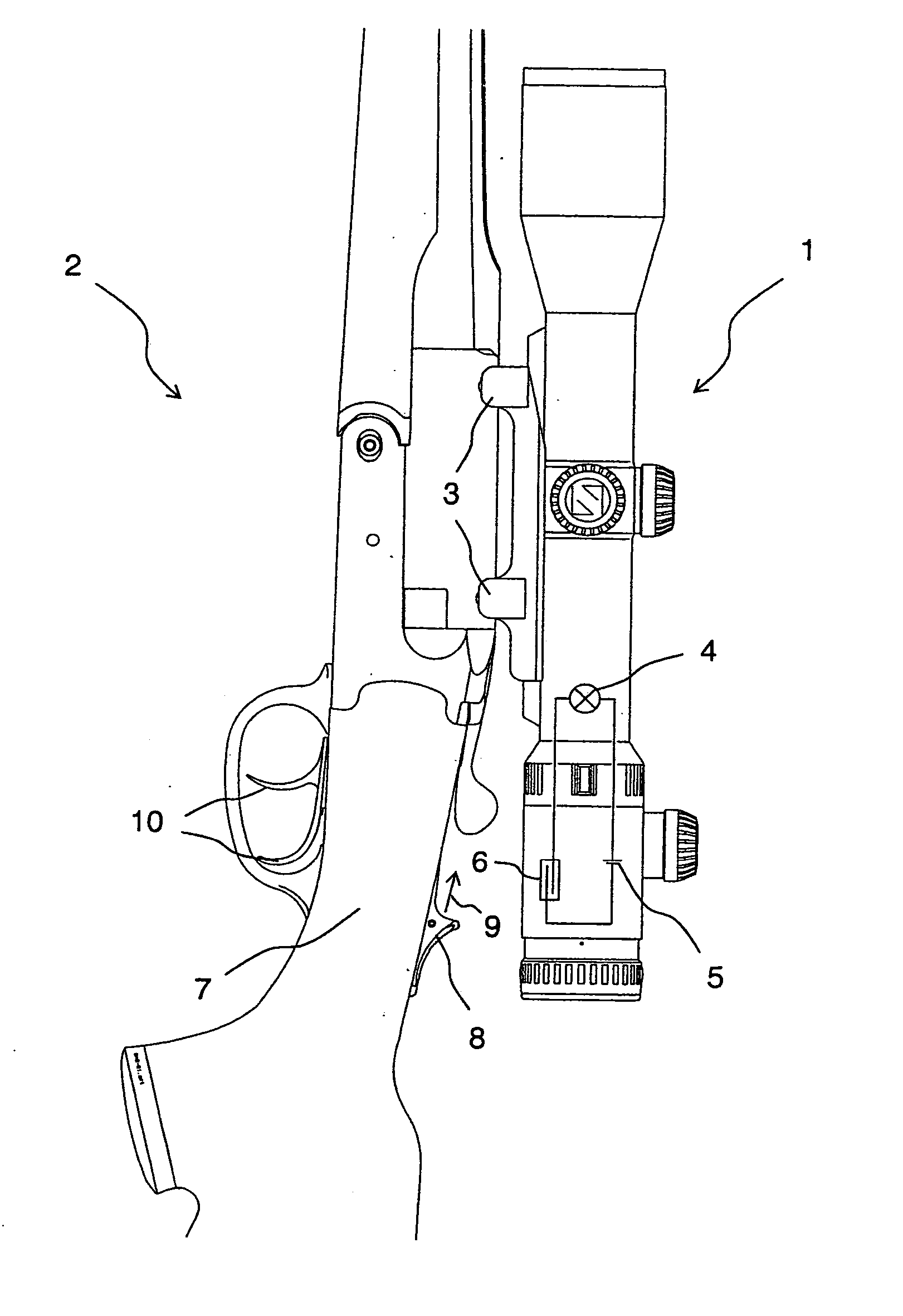
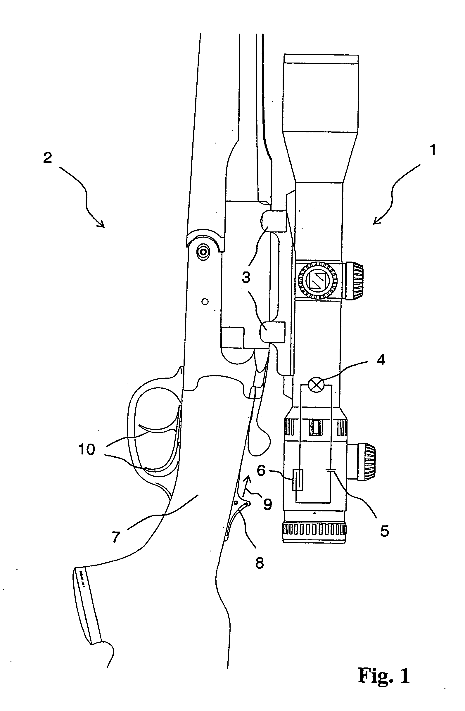
[0016]FIG. 1 shows a sighting device 1 in the form of a telescopic sight, which is attached to a firearm 2 in the form of a shotgun by means of a mount 3 of a known type. The sighting device 1 contains a reticle, for example, in the form of crosshairs, which can be partially illuminated, for example, by a bright point in the center. This illumination is generated by a light source 4, which concerns a light-emitting diode (LED). Possibilities for optical superimposition of a light point at defined points in the field of view of a telescopic sight are known and not of interest here. A battery 5 is used for supplying power to the light source 4. A switch 6 in the form of a reed contact is connected in the power circuit for powering the light source 4 by the battery 5. All of the elements belonging to this power circuit are installed in or on the sighting device 1. It is understood that the representation of said power circuit in FIG. 1 is schematic.

[0017] A reed contact is an electric...


PUM


Abstract

For a firearm sighting device with an electrical illumination device that can be turned on and off by means of a switch, the switch is embodied and arranged in or on the sighting device such that, for the conventional attachment of the sighting device on the firearm, the switch is activated mechanically to turn on the illumination device by the activation of an actuator provided in or on the firearm for setting the firearm into the armed state. By disabling the firearm, the switch is activated mechanically to turn off the illumination device. Preferably, the activation of the switch is performed using a non-contact method, for which, in particular, the configuration of the switch as a reed contact is suitable. The switch can also be part of a retrofit kit, by means of which a sighting device for a firearm can be equipped at a later time with the previously mentioned function. Here, the switch of the retrofit kit replaces a standard switch operated by hand separately from the firearm.

Description

FIELD OF THE INVENTION [0001] The invention relates to a sighting device for a firearm, i.e., a sighting device with an electrical illumination device which can be turned on and off by means of a switch. The invention also relates to a retrofit kit for a sighting device for a firearm. BACKGROUND OF THE INVENTION [0002] In modern telescopic hunting sights, there is a clear trend towards models with so-called illuminated reticles. In these configurations, a portion of the reticle, for example, the target point or the target circle, can be illuminated in order to increase the contrast of the reticle or a part of the reticle, according to its use. The energy source for the illuminated reticle is usually a battery located in the support of the illuminated reticle. Configurations found on the market are controlled on the device itself through a combination on / off switch and brightness controller. Such a sighting device is known from DE 199 13 461 A1, wherein the illumination device is in ...

Claims


Application Information

Patent Timeline
Patent Type & Authority Applications(United States)
IPC IPC(8): F41G1/34F41G1/38
CPCF41G1/34F41G1/38F41G1/345
Inventor SCHERPF, CHRISTIAN
Owner BLASER FINANZHLDG
Why Eureka
Try Eureka