
Ultrasonic seepage meter

a seepage meter and ultrasonic technology, applied in the direction of instruments, liquid/fluent solid measurement, volume/mass flow by dynamic fluid flow effect, etc., can solve the problem of inherently difficult quantification of sgd, the effect of reducing labor intensity and improving accuracy

Inactive Publication Date: 2005-11-17
GROUNDWATER SEEPAGE
View PDF1 Cites 3 Cited by
  • Summary
  • Abstract
  • Description
  • Claims
  • Application Information

AI Technical Summary

Benefits of technology

[0008] It is the object of the present invention to overcome the shortcomings of previous methods to quantify SGD. The invention is intended to provide a robust, time transient meter that is able to continuously record the wide range of seepage rates observed in the field while providing a less labor intensive and more accurate method of quantifying SGD in both the forward and reverse flow directions.
[0009] One advantage of the present invention is to be able to continuously record groundwater discharge in subsurface (intertidal and subsurface) environments. Another feature of the present invention is the ability to utilize velocity of sound data collected by the meter to determine The salinity and therefore source of the water passing through the seepage meter. This feature provides an advantage over other methods by differentiating terrestrial groundwater from surrounding surface water in marine environments. Therefore, the source of the discharge and any toxic or hazardous constituents present in the discharge is more easily determined and quantified. Another advantage of the present invention is the ability to accurately and continuously quantify very low flow rates regardless of changes in the temperature, density or the affect of ebullition of gases from the sediments.

Problems solved by technology

This discharge carries with it contaminants and / or nutrients, dissolved and / or colloidal, that have the potential to impact the chemical budget of surface water ecosystems.
A major obstacle in studying SGD is accurately measuring groundwater seepage across the sediment-water interface.
Discharge rates may be as low as <1 cm / day and these low rates make quantification of SGD inherently difficult.
In addition, the ebullition of gas from sediments is a common event, further increasing the difficulty of accurately measuring SGD.
Although this method can be effective, various errors have been associated with the device that must be corrected for prior to sampling.
Another disadvantage to this method is that it is quite labor intensive since the plastic bags need to be monitored and replaced continuously.
In addition, data collected are averages over the specified time interval and may not fully quantify short term events.
Furthermore, this method is incapable o measuring reverse flow.
This method, however, cannot be monitored during deployment and may therefore malfunction during the collection period without notice.
Another disadvantage of this method is that it cannot measure seepage in intertidal environments in which the seepage meter becomes periodically air bound during low tide events.
In addition, variations in the water density and temperature can also affect the accuracy of the heat pulse method.
However, this method is not a direct measurement of seepage but and estimate based on head measurements and sediment conductivity.

Method used


Image

  • Ultrasonic seepage meter
  • Ultrasonic seepage meter
  • Ultrasonic seepage meter

Examples


Embodiment Construction

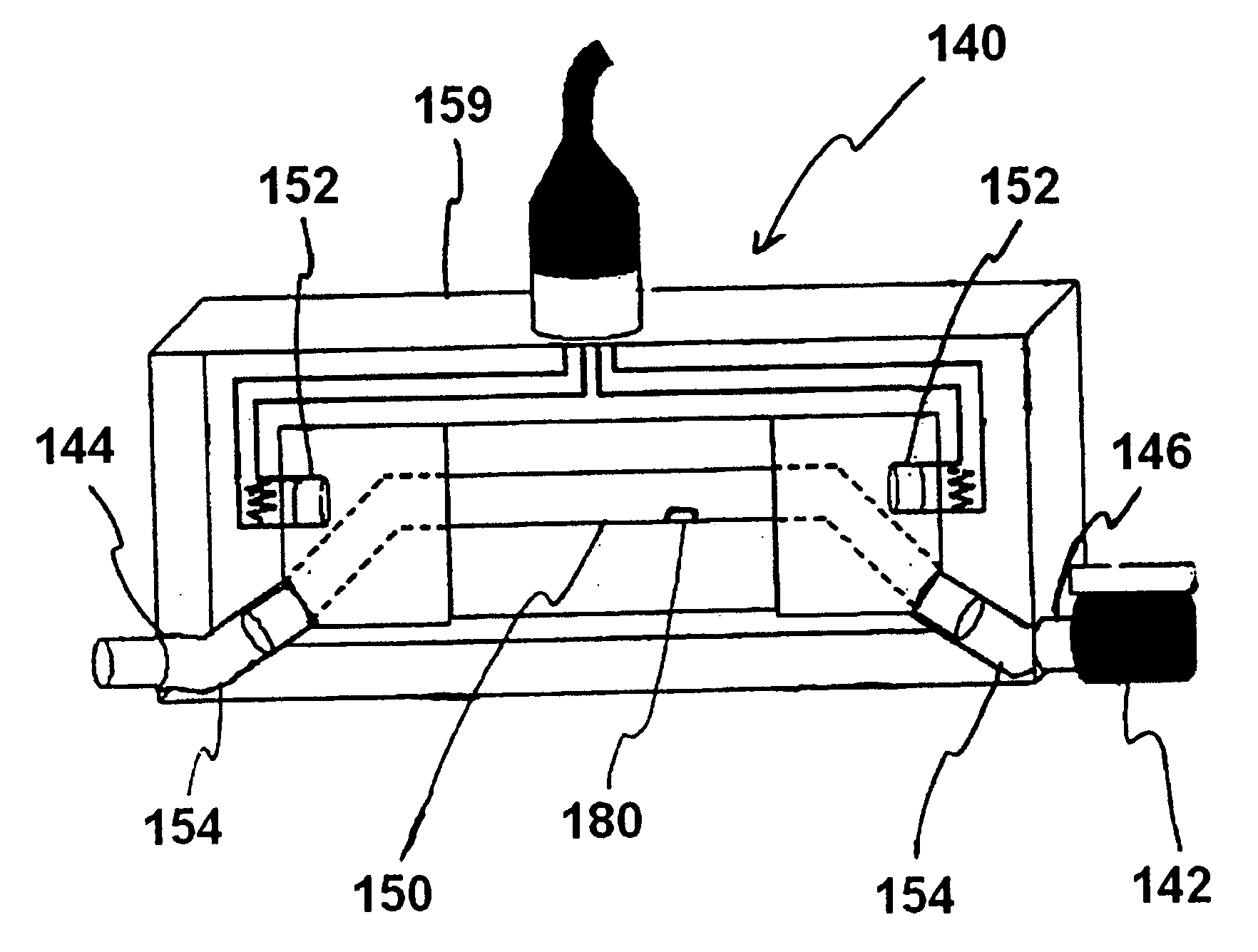
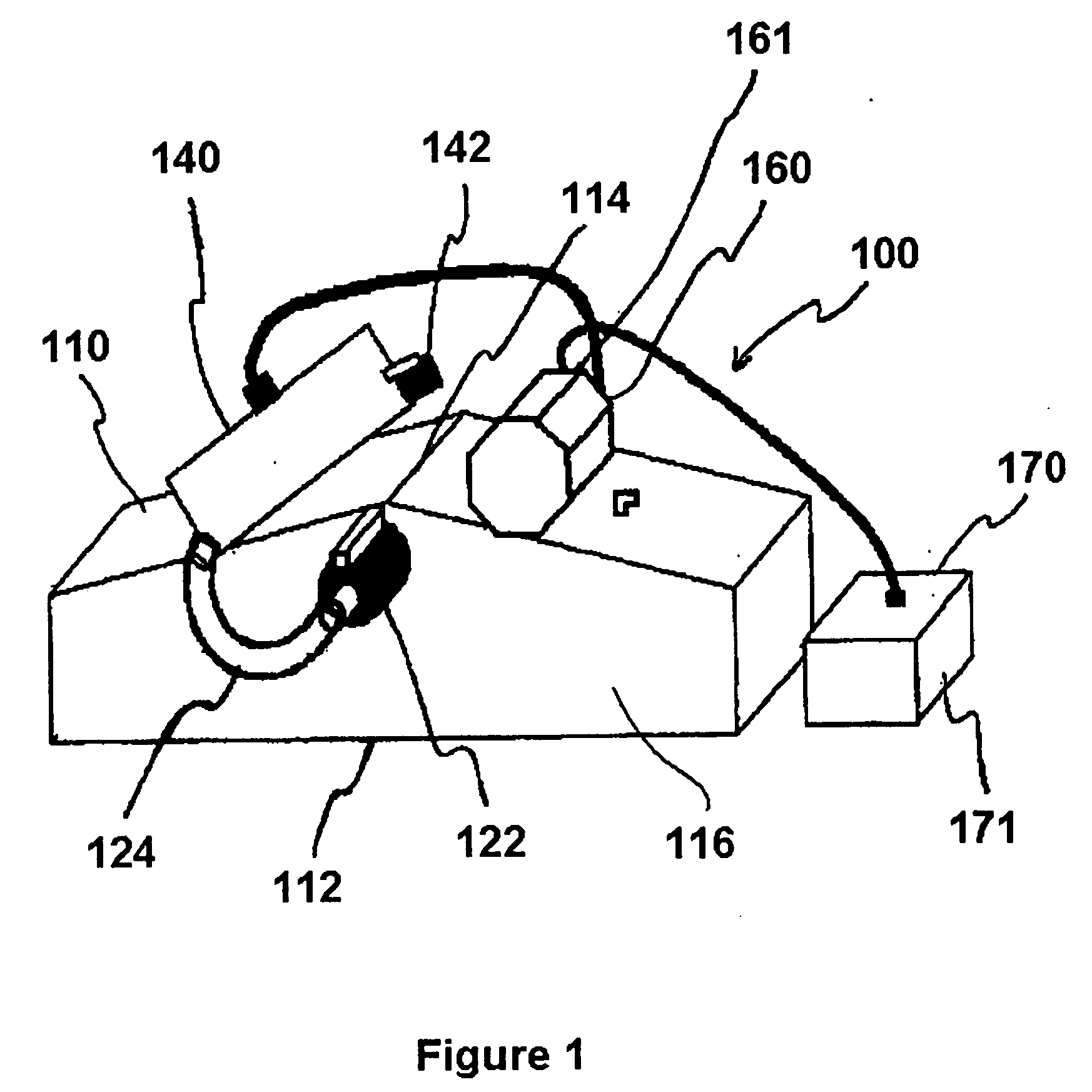
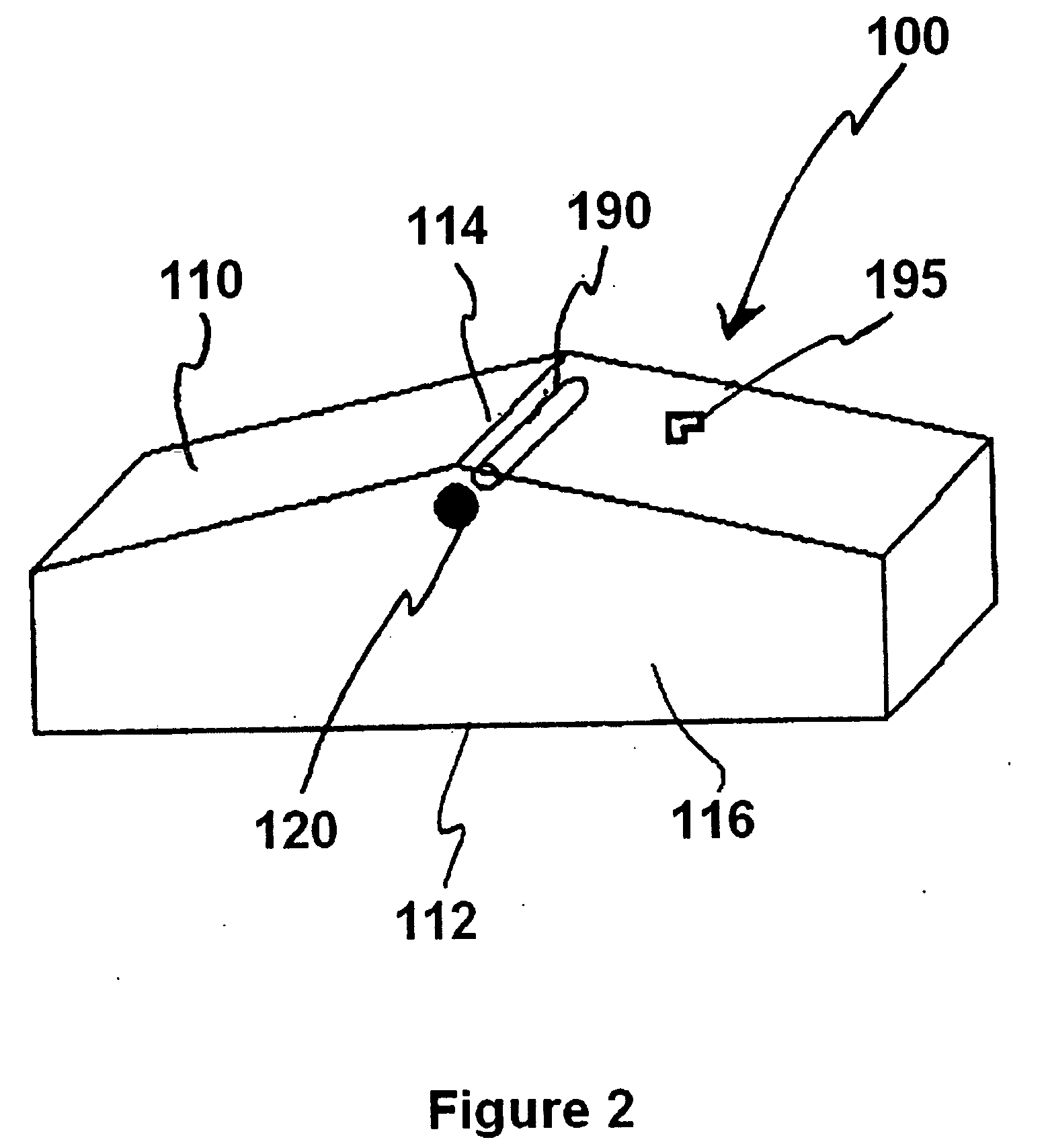
[0018]FIGS. 1 and 2 illustrate a preferred embodiment of an ultrasonic seepage meter 100 in accordance with the present invention. Generally, ultrasonic seepage meter 100 comprises collection funnel 110, flow meter 140, and controller logger 160. Collection funnel 110, as shown in FIGS. 1 and 2, further comprises an open bottom 112 and an enclosed top 114. The sides of collection funnel 110 form a square, each side being 0.46 m in length (corresponding to a capture area A=0.21 m2), and at least 10 cm tall. However, it can be appreciated that collection funnel 110 may be of many different types of geometries and still be within the spirit of the present invention. Extending from side 116 of funnel 110 is discharge outlet 120. Discharge outlet 120 may also further comprise valve 122, which may be a ball valve. In a preferred embodiment, the top 114 of funnel 110 is angled so that the side 116 with discharge outlet 120 is slightly higher than the other side of funnel 110 (see FIG. 4). ...


PUM


Abstract

An ultrasonic flow meter has been adapted for such measurements in the submarine environment. Connected to a collection funnel, the meter houses two piezoelectric transducers mounted at opposite ends of a cylindrical flow tube. By monitoring the perturbations of fluid flow on the propagation of sound waves inside the flow tube, the ultrasonic meter can measure both forward and reverse fluid flows in real time. Laboratory and field calibrations show that the ultrasonic meter can resolve groundwater discharges in both the forward and reverse directions on the order of 0.1 μm / s (<1 cm / d), and it is sufficiently robust for deployment in the field for several days. Data collected with the meter elucidate the temporal and spatial heterogeneity of submarine groundwater discharge and its interplay with tidal loading and other driving forces. A negative correlation between the discharge and tidal elevation can be observed.

Description

FIELD OF THE INVENTION [0001] The present invention relates to an apparatus and method for measuring the velocity and other characteristics of submarine groundwater discharge as it enters or exits a surface water body, and more particularly to a remotely deployable time transient seepage meter that utilizes ultrasonic technology to continuously quantify and record the measured information. The present invention is intended for use in environmental fields including hydrology, oceanography, geology, ecology and all other related fields. BACKGROUND OF THE INVENTION [0002] Understanding the exchange between seepage and overlying surface water has become increasingly important due to the potential impacts to the environment resulting from anthropogenic land uses. The key input for submarine groundwater discharge (SGD) in near-shore environments is believed to be the discharge from land to surface water induced by the hydraulic gradient in the terrestrial aquifer. However, significant con...

Claims


Application Information

Patent Timeline
Patent Type & Authority Applications(United States)
IPC IPC(8): G01F1/32G01F1/66G01V9/02
CPCG01V9/02G01F1/662Y02A90/30
Inventor SMITH, CHRISTOPHERPAULSEN, RONALDWONG, TENG-FONG
Owner GROUNDWATER SEEPAGE
Learn More