Collapsible track undercarriage for installation and tensioning

a technology of track and undercarriage, which is applied in the direction of mechanical equipment, transportation and packaging, and gearing, etc., can solve the problems of large tensioning force, affecting the installation and tensioning of the track, and reducing the wrapping angle of the track around the sprocket or roller, so as to reduce the tensioning force and the effect of reducing the tensioning for

Active Publication Date: 2005-11-17
CLARK EQUIP CO INC
View PDF7 Cites 42 Cited by
  • Summary
  • Abstract
  • Description
  • Claims
  • Application Information

AI Technical Summary

Benefits of technology

[0009] The present invention uses a roller wheel assembly located between the undercarriage frame and the upper track portion, with tensioning wheels that are mounted on pivoting brackets or

Problems solved by technology

The springs also compress a limited amount when objects get between the track and the support wheels or undercarriage, or when there is some other large, sudden load on the track.
Due to the large wrap angle of the track that spans over the adjustable front or rear idlers in prior art systems

Method used


Image

  • Collapsible track undercarriage for installation and tensioning
  • Collapsible track undercarriage for installation and tensioning
  • Collapsible track undercarriage for installation and tensioning

Examples


Embodiment Construction

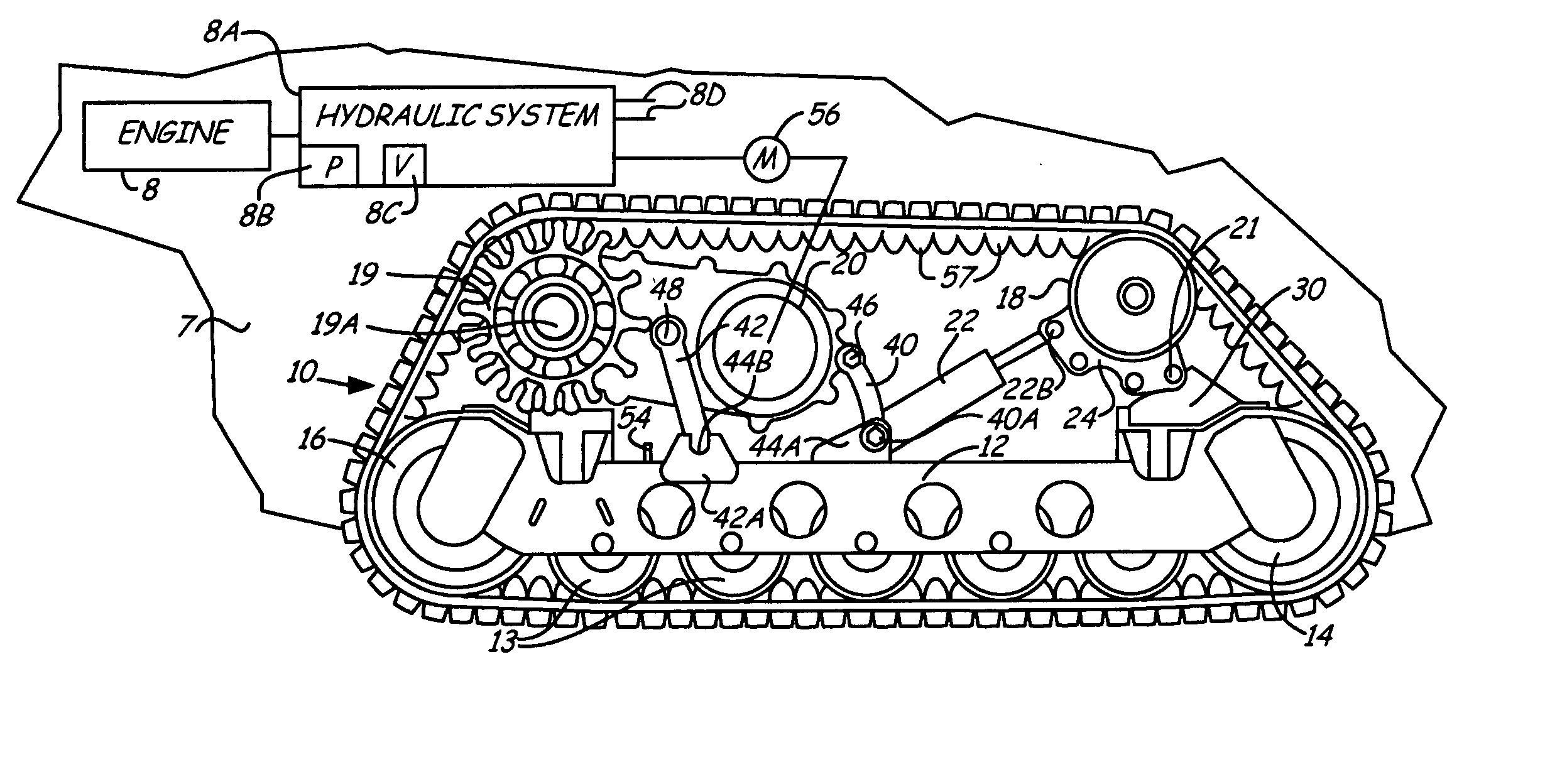
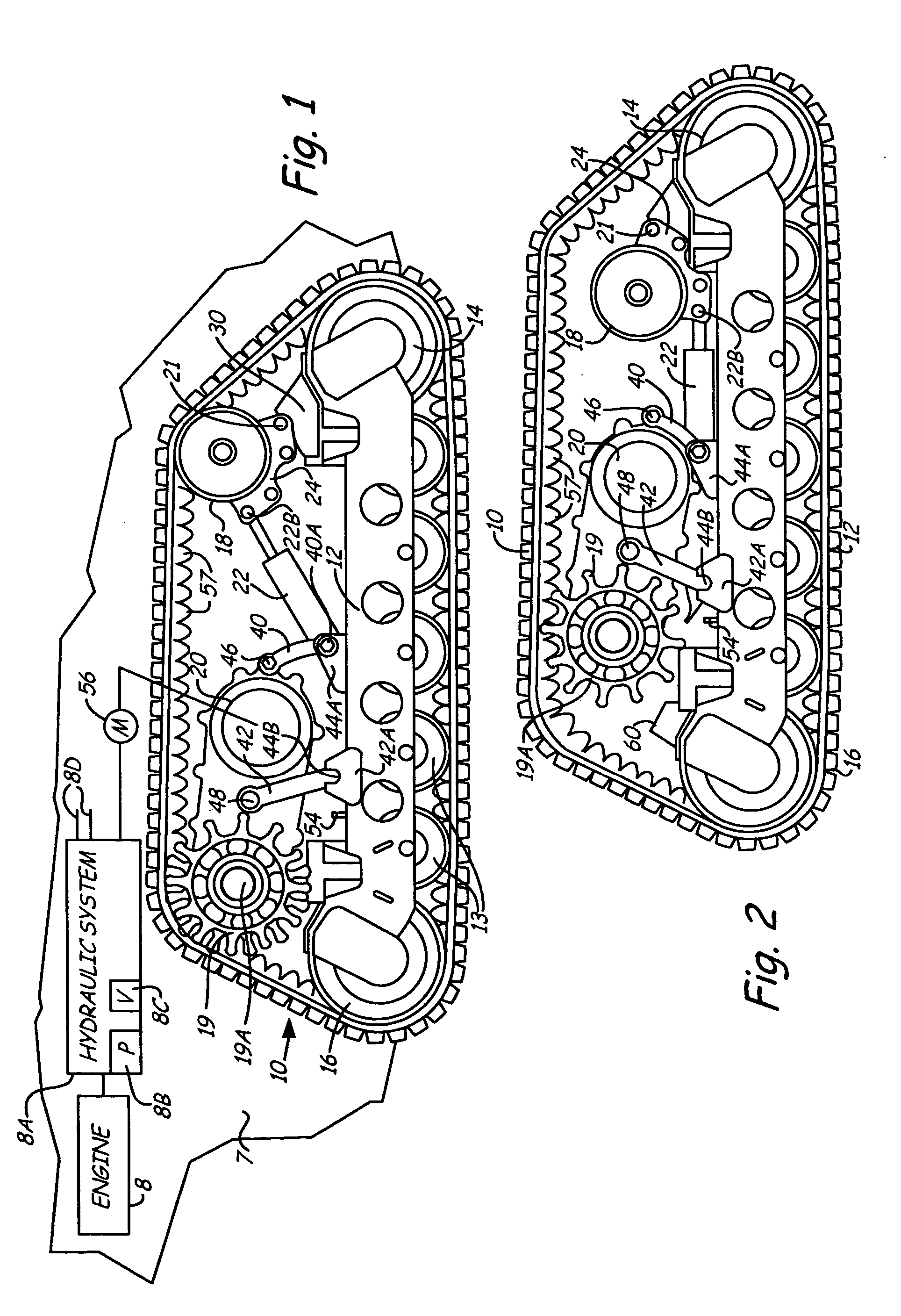
[0027] In FIG. 1, a compact loader shown at 7 is illustrated only schematically, and is of a conventional design. The loader is powered with an engine 8, to provide power to a hydraulic system 8A including a pump 8B, suitable valves 8C, and various hydraulic controls that would be connected along lines 8D. The valves 8C control motors 56 that are used for driving the input shafts of suitable drive chain cases or gear drives for driving tracks 10, as shown, a rubber track on each side of the frame 7.

[0028]FIG. 1 is shown with the track on one side of the loader in a working or operating position. The track frame or undercarriage 12 is attached in a suitable manner to the loader body or frame 7. The track frame 12 supports bogie wheels 13, that are mounted on the frame 12 for supporting the lower length of the track 10. The track frame 12 also supports a rotatable, but fixed position, front idler roller 14, and a rear idler roller 16. The front upper portion of the track 10 is held i...


PUM


Abstract

A track frame or undercarriage is made to support a rubber track on suitable guide rollers. A tensioning roller is provided as one of the guide rollers on the interior of the track and is mounted on a pivoting bracket. The pivoting bracket moves the tensioning roller to a working position for creating tension in the track. An actuator provides a known force on the pivoting bracket to move the tensioning roller to its working position, using a controlled pressure applied to the actuator. Drive sprockets for the track are mounted onto a drive case that is mounted to the frame through pivoting linkages such that the drive case and the drive sprocket can be held in a working position and retracted away from the track. The position of the tensioning roller is maintained within set limits of retractions during use, by providing a stop to limit the amount that the tensioning roller can retract.

Description

[0001] This application is based upon and claims priority from U.S. Provisional Application Ser. No. 60 / 570,333, filed May 12, 2004, the content of which is incorporated by reference.BACKGROUND OF THE INVENTION [0002] The present invention relates to a mounting system for an endless drive track used in a crawler type vehicle, such as a loader, tractor or the like. The mounting system comprises an undercarriage that includes pivotally moveable track rollers that support the track under tension in one position and loosen the track in another position so that the track can be taken off the support rollers and re-installed, and then, when desired, the rollers are pivoted back to a position to maintain a desired tension in the track. [0003] In the prior art, the use of track drives for various vehicles including tractors and self propelled loaders has been expanding. Track laying vehicles have been well known for years, and generally do include guide rollers or sprockets that will guide ...

Claims


Application Information

Patent Timeline
IPC IPC(8): B62D55/12B62D55/14B62D55/30B62D55/32F16J1/10
CPCB62D55/12B62D55/32B62D55/305B62D55/14
Inventor ALBRIGHT, LARRY E.FREDERICK, DANKOCH, RODNEYWEHSELER, ANDREW A.
Owner CLARK EQUIP CO INC
Why Eureka
Try Eureka