Mechanical limiter switch

a limiter switch and mechanical technology, applied in the direction of contact mechanism, coupling device connection, therapy, etc., can solve the problems of limited use of electrical devices, minimally invasive surgical devices, and the use of these devices

Active Publication Date: 2005-11-17
ATL TECH LLC
View PDF15 Cites 81 Cited by
  • Summary
  • Abstract
  • Description
  • Claims
  • Application Information

AI Technical Summary

Problems solved by technology

Clearly, this method relies upon the user to adhere to those regulations subject to penalties for non-compliance.
Thus, this is only a self-adhering method to limit the use of these devices.
Minimally invasive surgical devices comprise most of the electrical devices whose use is limited by regulatory action.
These devices can be expensive and reimbursement for their use can be tightly controlled by health insurance.
Further, in many parts of the lesser-developed countries of the world, availability can be limited.
The tracking system, along with the threat of lawsuit, creates a barrier to misuse.
However, outside of the US where the tort system is not as well developed, multiple misuses can occur with greater frequency.
These factors present a potential liability for the manufacturer of these devices along with the associated tarnishing of goodwill and reputation to the manufacturer.
First, they cannot be used to retrofit existing devices easily.
X rays potentially can destroy integrated circuits and / or alter the content of memory and integrated circuits, thereby altering the software in an uncontrollable manner.

Method used


Image

  • Mechanical limiter switch
  • Mechanical limiter switch
  • Mechanical limiter switch

Examples


Embodiment Construction

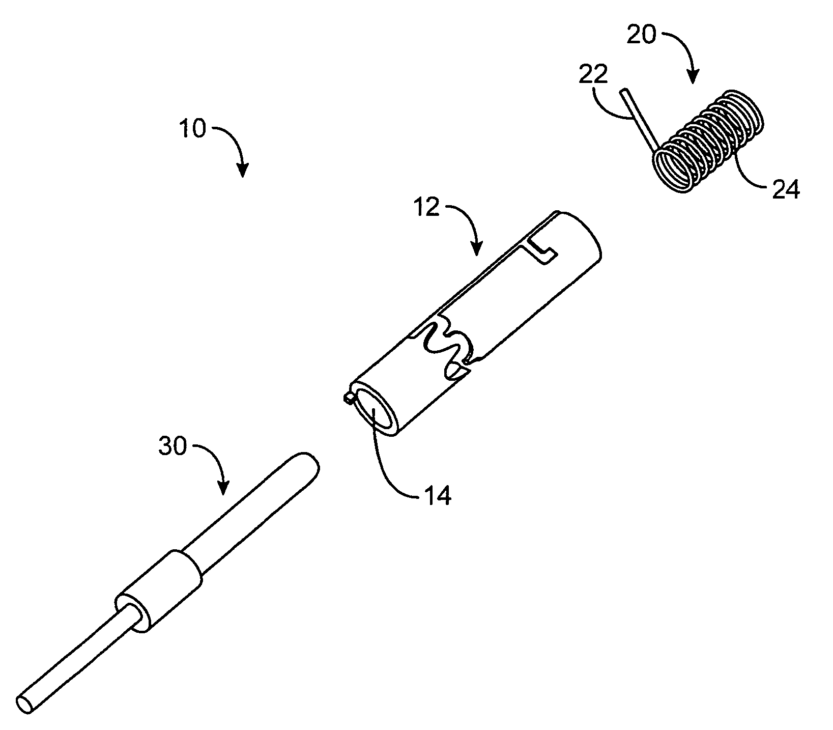
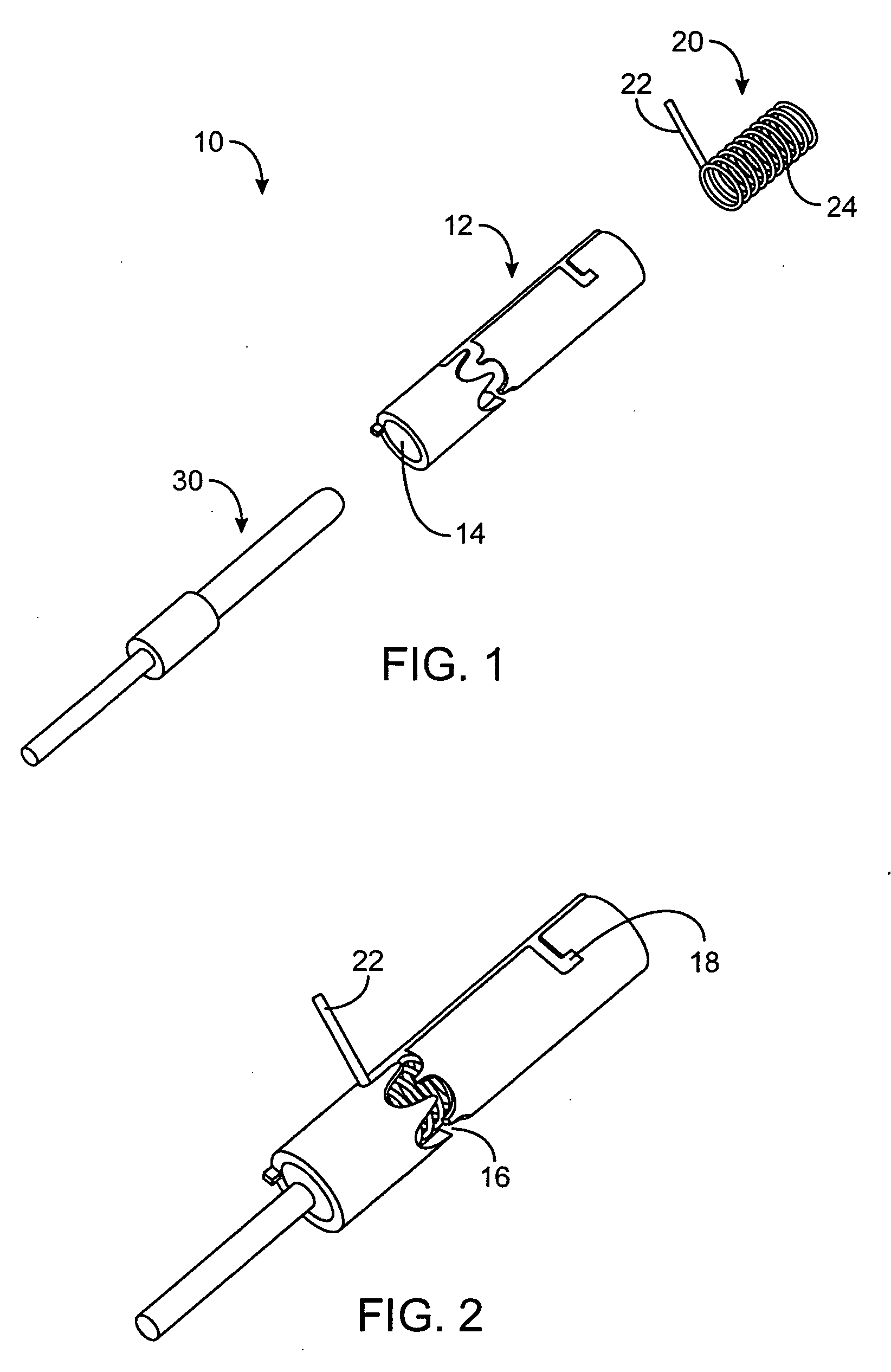
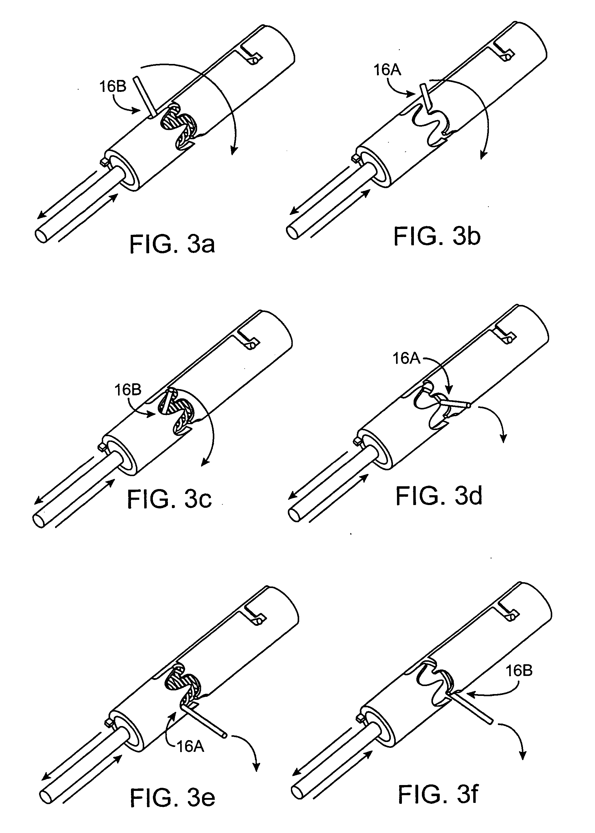
[0023] Referring to FIG. 1, there is shown an exploded view of a mechanical limiter switch 10 of the present invention. The switch 10 comprises a housing 12, which is substantially cylindrically shaped and has an outer perimeter, and an opening 14 in an axial direction. The housing 12 has a pattern 16 along its perimeter. In a preferred embodiment, the pattern 16 is zigzag shaped; having crests 16a and troughs 16b (shown in FIG. 6b). The housing 12 also has a notch 18 (shown in FIG. 2). A spring 20 is positioned axially in the opening 14 of the housing 12. The spring 20 has a member 22 near a first end, which extends radially from the spring 20. The spring 20 has a second end 24. The spring 20 is mounted in the axial opening 14 of the housing 12 such that the second end 24 is anchored in the notch 18, and the member 22 protruding through the pattern opening 16 of the housing 12. When the spring 20 is so positioned, it is pre-tensioned in the radial direction. Thus, as the spring 20 ...


PUM


Abstract

A mechanical limiter switch for use in a medical or surgical device has a substantially cylindrically shaped housing with a perimeter and an opening in an axial direction. The housing has a pattern along the perimeter. A spring is mounted in the opening along the axial direction, and is pre-stressed for movement in a radial direction and pre-stressed for movement in the axial direction. The spring has a radial member protruding through the pattern of the housing. A plunger is mounted in the opening along the axial direction, abutting the spring for urging the spring in the axial direction and for moving the member in the pattern along the perimeter. After a pre-determined number of activations of the plunger in the axial direction, the member will come to a terminating position and will either contact a pin to establish electrical continuity or at the terminating position break electrical continuity.

Description

[0001] This application claims the priority of a co-pending provisional application 60 / 434,297 filed on Dec. 17, 2002.TECHNICAL FIELD [0002] The present invention relates to a mechanical limiter switch and more particularly to a limiter switch for use in a medical or surgical device wherein said switch limits the operation of the device after a pre-determined number of operations. BACKGROUND OF THE INVENTION [0003] Current methods to limit the number of uses of electrical devices, such as those used in surgical procedures or other health or medical related applications have relied upon regulatory actions, such as regulations promulgated by the United Stated FDA and the European Regulatory body (EUR). Clearly, this method relies upon the user to adhere to those regulations subject to penalties for non-compliance. Thus, this is only a self-adhering method to limit the use of these devices. [0004] Minimally invasive surgical devices comprise most of the electrical devices whose use is ...

Claims


Application Information

Patent Timeline
Patent Type & Authority Applications(United States)
IPC IPC(8): A61N1/04H01H13/18H01R13/703H01R13/707
CPCA61B2560/0276A61N1/048H01H13/18H01H2003/0273H01R2201/12H01R13/7032H01R13/7035H01R13/707H01H2300/014
Inventor KENT, HAROLD B.LEVANTE, JAMES J.FINE, AARON T.LAYTON, JOSEPH R.
Owner ATL TECH LLC
Why Eureka
Try Eureka