Flow device

a flow device and flow technology, applied in flow mixers, special dispensing means, electrolysis, etc., can solve the problems of shrinkage of polymeric compositions, difficulty in changing the surface chemistry of packing materials after they have been placed in channels,

Inactive Publication Date: 2005-11-17
TELEFLEX LIFE SCI PTE LTD
View PDF61 Cites 27 Cited by
  • Summary
  • Abstract
  • Description
  • Claims
  • Application Information

AI Technical Summary

Benefits of technology

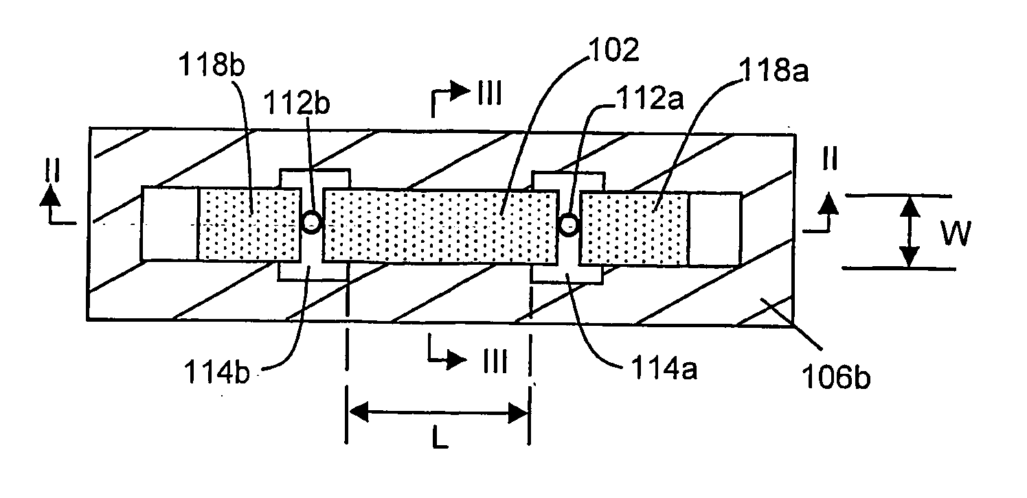
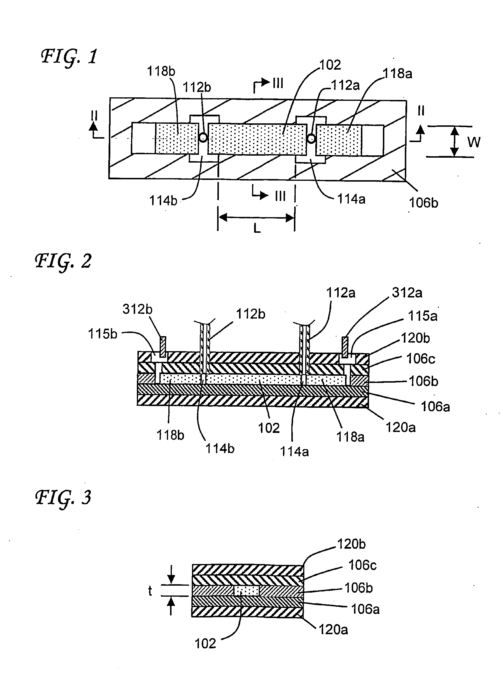
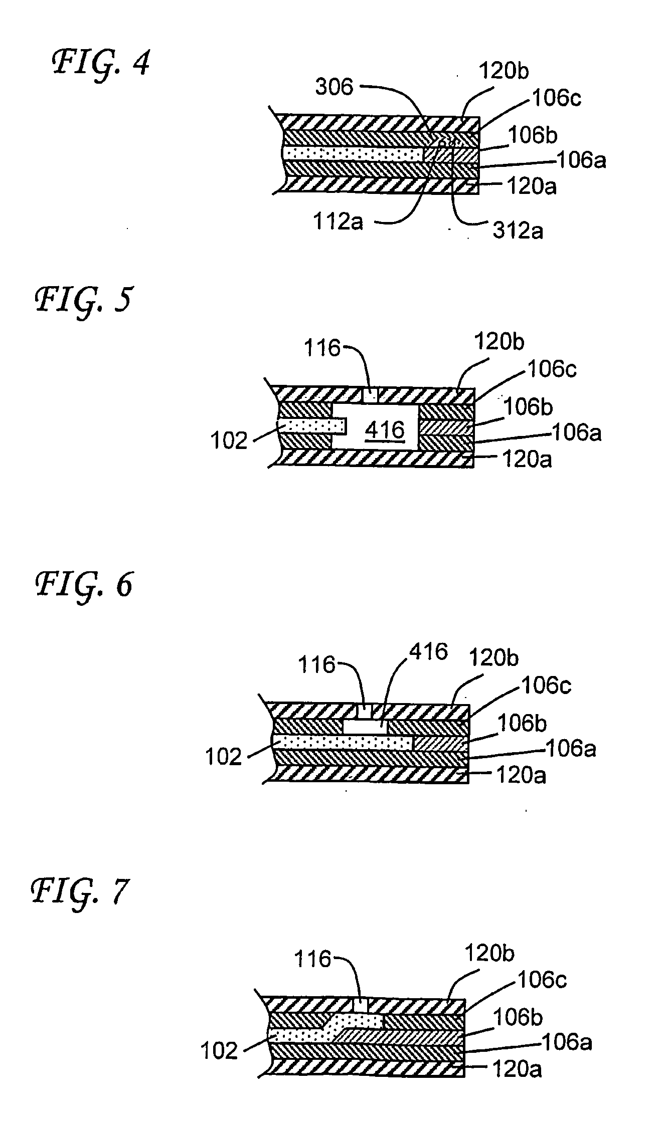
[0005] We have discovered, in accordance with the present invention, a wide variety of novel flow devices which make use of solid porous materials as liquid flow media. The invention is particularly useful when pre-shaped porous materials are used to provide conduits in flow devices, but the invention is not limited to pre-shaped porous materials. The term “pre-shaped” is used to denote a member having a shape before it is enclosed by the barrier member, as distinct from a member which is shaped within the conduit. The porous materials are often lami

Problems solved by technology

These methods suffer from various disadvantages, for example the need to prevent the packing materials from falling out of the channel and/or falling into adjacent channels or other

Method used


Image

  • Flow device
  • Flow device
  • Flow device

Examples


examples 1-3

[0138] Three devices as illustrated in FIG. 19 were constructed using first and second PFMs having the characteristics shown in the Table below, the dimensions of L, w and t being in mm. In each Example, the effective pore size of the first PFM was 240 nm and the effective pore size of the second PFM was 300 nm.

First PFMSecond PFMExample #LwtZetaLwtZeta11050.1+50102.10.12−3021050.1+50580.2+23102.30.1−358.752.30.09+27

example 4

[0139] A mixing device as shown in FIGS. 23-25 was prepared. The dimensions of the device, as identified in FIGS. 23-25 and given in mm, are shown in the table below. Each of the PFMs was a hydrophilic PVDF membrane having effective pore size of about 800 nm. The mixing member was a hydrophilic PVDF membrane having an effective pore size of about 6000 nm and a thickness of 0.1 mm.


PUM

PropertyMeasurementUnit
Fractionaaaaaaaaaa
Fractionaaaaaaaaaa
Fractionaaaaaaaaaa

Abstract

Liquid flow devices, particularly microfluidic devices, containing solid porous materials. Flow in the devices can be pressure-driven flow and/or electroosmotic flow. The porous materials are preferably pre-shaped, for example divided from a sheet of porous material, so that they can be assembled with liquid-impermeable barrier materials around them. The devices can for example be prepared by lamination. A wide variety of devices, including mixing devices, is disclosed. A mixing device is illustrated in FIG. 23.

Description

RELATED APPLICATION DATA [0001] This application is a continuation-in-part of our application Ser. No. 10 / 198,223, filed Jul. 17, 2002 (Docket No. 14138), the entire disclosure of which is incorporated herein by reference.FIELD OF THE INVENTION [0002] This invention relates to flow devices. BACKGROUND OF THE INVENTION [0003] Many systems make use of flow devices, including micro-flow devices, which include a conduit through which there is electroosmotic and / or pressure-driven flow of a liquid. Such systems include, for example, chromatography systems, including high-performance liquid chromatography (HPLC) systems, electrokinetic (also known as electroosmotic) pumping systems, chemical processing systems, and electrophoric separation systems. Reference may be made for example to U.S. Pat. Nos. 6,074,725, 6,156,273, 6,176,962 and 6,287,440, and International Publication Nos. WO 99 / 16162 and WO 02 / 101474, the entire disclosures of which are incorporated herein by reference for all pur...

Claims


Application Information

Patent Timeline
IPC IPC(8): B01D61/18G01N37/00B01F5/06B01F13/00B01F15/02B01J19/00B01L3/00B67D99/00F04B19/00F04B43/04F04B43/06F15C5/00F16K99/00G01N27/447G01N30/02G01N30/28G01N30/32G01N30/34G01N30/46G01N30/52G01N30/60
CPCB01D61/18Y10T156/1046B01F5/0692B01F13/0076B01F15/0201B01F15/0232B01L3/5023B01L3/502707B01L3/502753B01L2300/0645B01L2300/0654B01L2300/0681B01L2300/0877B01L2300/0887B01L2400/0418F04B19/006F04B43/043F04B43/06F16K99/0001F16K99/0025F16K99/0049G01N27/44791G01N30/461G01N30/6065G01N30/6095G01N2030/027G01N2030/285G01N2030/326G01N2030/347G01N2030/525G01N2030/528B01F5/0682B01F25/45221B01F25/45B01F33/3031B01F35/7172B01F35/71
Inventor PAUL, PHILIP H.NEYER, DAVID W.REHM, JASON E.
Owner TELEFLEX LIFE SCI PTE LTD
Why Eureka
Try Eureka