Electrolyte-separating membrane for selective transfer of cations through the membrane and process for manufacturing said membrane
A desalination and brine technology, applied in the field of desalination devices, can solve the problems of excessive cost, large amount of energy, and high cost
- Summary
- Abstract
- Description
- Claims
- Application Information
AI Technical Summary
Problems solved by technology
Method used
Image
Examples
Embodiment 1
[0122] Example 1: Desalination Using a Microfluidic Amphoteric Electrode Device
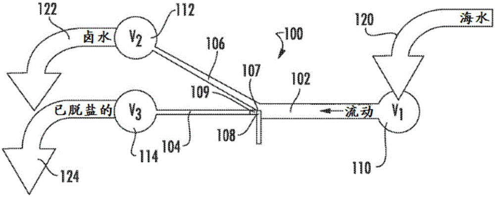
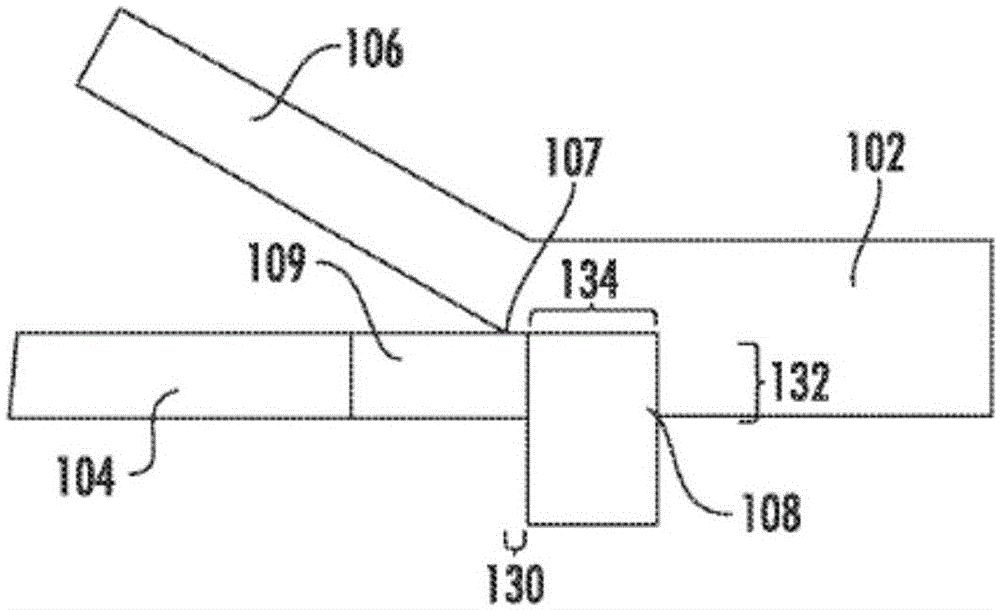
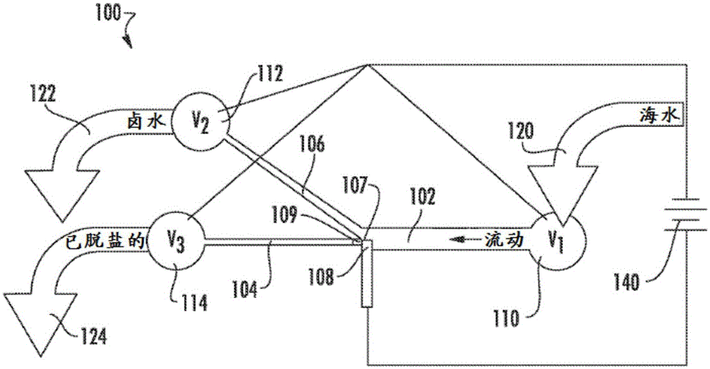
[0123] An ultramicroelectrode electrochemical cell comprising a desalination cell spanned by a single bipolar electrode (BPE) and auxiliary channels is used to desalinate seawater along a locally generated electric field gradient in the presence of pressure-driven flow (PDF). Seawater desalination is achieved by applying a bias voltage between parallel desalination cells and auxiliary channels to drive chloride oxidation at the anode of the bipolar electrode. At the cathode, water reduction occurs to support current flow.
[0124] Oxidation of chloride at the anode of the BPE leads to an ion depletion region and subsequent electric field gradient. The electric field gradient directing the ions through the desalination cell into the branched microchannels creates a brine flow, while the desalinated water continues to flow forward when the rate of pressure-driven flow is controlled. Therefore, se...
Embodiment 2
[0154] Example 2: Desalination using a microfluidic electrode device
[0155] Fabrication of Microfluidic Devices
[0156] PDMS / glass hybrid microfluidic devices were prepared using microfabrication methods known in the art. The structure of the microfluidic device is schematically shown in FIG. 1 . The device includes a desalination unit and a single electrode.
[0157]Ti electrodes were coated with Pt on glass slides (1 inch x 1 inch). The photoresist was spin coated onto slides at 3500 rpm for 45 seconds, followed by soft baking on a hot plate at 100° C. for 1 minute to remove excess solvent. The device was then exposed to a UV lamp with a patterned mask on top to reveal the electrode (100 μm wide by 6.3 mm long) design. Excess photoresist is then removed by developing to expose the original glass. The device was then placed in an e-beam vacuum chamber where the first 10 nm of Ti was deposited. Then, 100 nm of Pt was deposited to form a Pt electrode. Excess photoresi...
Embodiment 3
[0165] Example 3: Desalination Simulation
[0166] Fabrication of Microfluidic Devices
[0167] In addition to the examples above, numerical simulations were used to model desalination. A computational approach was used to model the desalination of a 50mS / cm NaCl solution, similar to Figure 10B Example 1. The three-dimensional geometry of the simulated system is (5.0 mm long and 22 μm high), with 100 μm wide inlet channels and 50 μm wide dilute and concentrate outlet channels. Computer models simulate the flow initiated in the desalination channel and the distribution of local ion concentrations and local electric fields. Cl – Oxidation is assumed to be a Faradaic reaction occurring only at the anode. Developing the model based on a numerical scheme with inherent parallelism allows simple implementation at modern high-performance computing platforms (supercomputers).
[0168] The model is based on equations describing hydrodynamic, mass / charge transport and electrostati...
PUM
| Property | Measurement | Unit |
|---|---|---|
| width | aaaaa | aaaaa |
| width | aaaaa | aaaaa |
| height | aaaaa | aaaaa |
Abstract
Description
Claims
Application Information
 - R&D
- Intellectual Property
- Life Sciences
- Materials
- Tech Scout
- Unparalleled Data Quality
- Higher Quality Content
- 60% Fewer Hallucinations
Browse by: Latest US Patents, China's latest patents, Technical Efficacy Thesaurus, Application Domain, Technology Topic, Popular Technical Reports.
© 2025 PatSnap. All rights reserved.Legal|Privacy policy|Modern Slavery Act Transparency Statement|Sitemap|About US| Contact US: help@patsnap.com


