Device and method for combined microfluidic-micromagnetic separation of material in continuous flow

a micro-magnetic and material separation technology, applied in the field of systems and methods for separating materials from biological fluids, can solve the problems of affecting the normal functioning of blood cells, so as to minimize the disturbance of normal blood cells

Active Publication Date: 2009-09-03
PRESIDENT & FELLOWS OF HARVARD COLLEGE +1
View PDF16 Cites 109 Cited by
  • Summary
  • Abstract
  • Description
  • Claims
  • Application Information

AI Technical Summary

Benefits of technology

[0008]The present invention provides technologies for magnetic separation of living cells from biological fluids such as blood, cerebrospinal fluid, urine, and the like. The present invention can be used in portable devices for in-field diagnosis or therapy of diseases caused by blood-borne and other pathogens, such as sepsis and the like. The device and method of the present invention may be employed as on-chip magnetic separation and be used for isolating rare cells, such as cancer cells, stem cells, or fetal cells in the maternal circulation, and the like. The present invention incorporates nanoscale magnetic particles into biological fluids in continuous flow. The biocompatible magnetic nanoparticles bind pathog

Problems solved by technology

However, the loading capacity of these devices is limited because accumulation of the collected particles can restrict fluid flow or lead to irreversible entrapment of samples, and the use of these systems is hampered by the need to disrupt continuous operation for sample elution.
However, because each magnet needs to be individually fabricated and positioned, further miniaturization and multiplexing is not possible with this approach.
Macroscale HGMCs have been used in magnetic separations for biomedical applications (Chalmers et al., 1998; Fuh and Chen, 1998; Hartig et al., 1995; Melville et al.

Method used


Image

  • Device and method for combined microfluidic-micromagnetic separation of material in continuous flow
  • Device and method for combined microfluidic-micromagnetic separation of material in continuous flow
  • Device and method for combined microfluidic-micromagnetic separation of material in continuous flow

Examples


Embodiment Construction

[0015]The following detailed description of the invention refers to the accompanying drawings and to certain embodiments, but the detailed description of the invention does not limit the invention. The scope of the invention is defined by the appended claims and equivalents as it will be apparent to those of skill in the art that various features, variations, and modifications can be included or excluded based upon the requirements of a particular use.

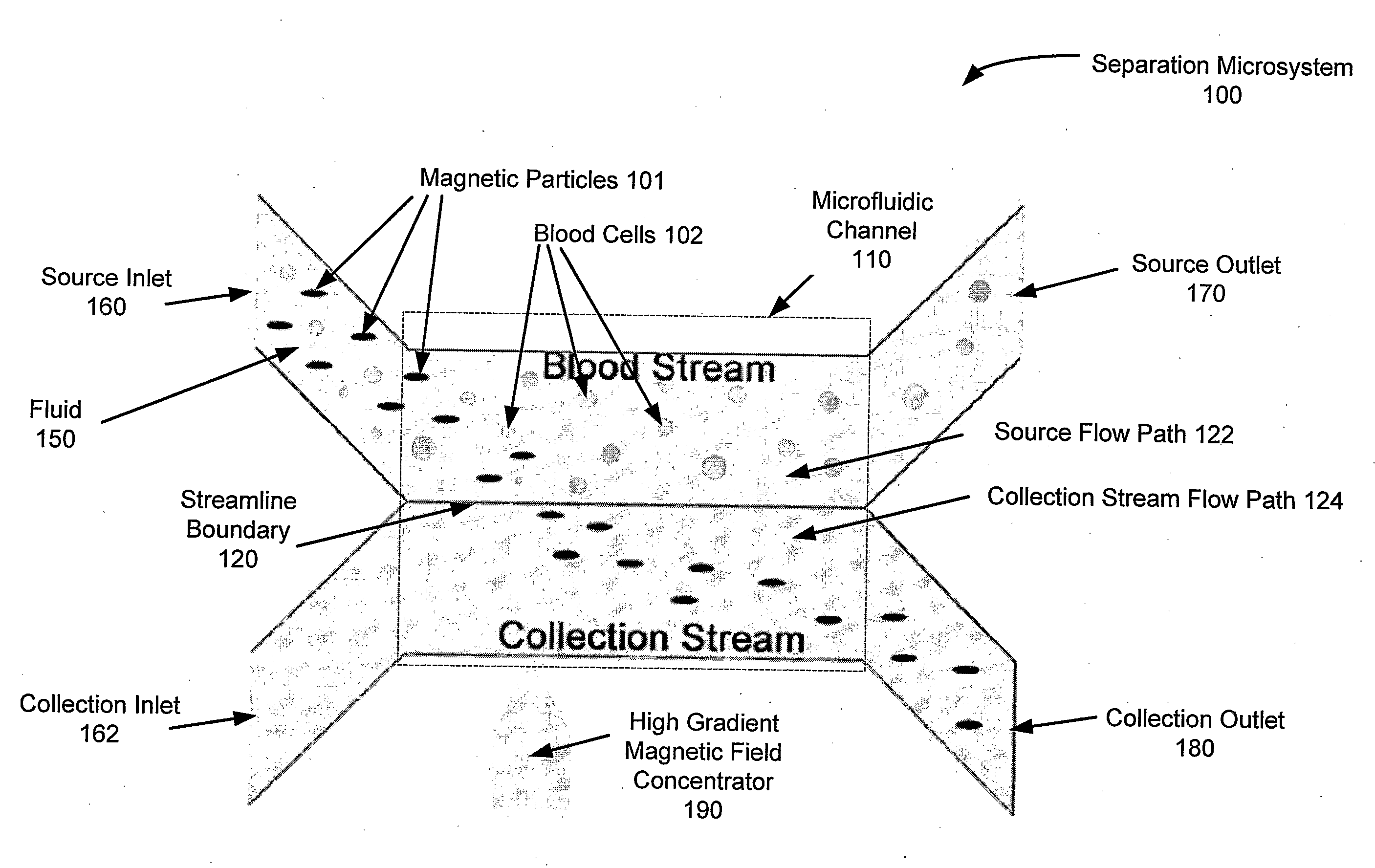
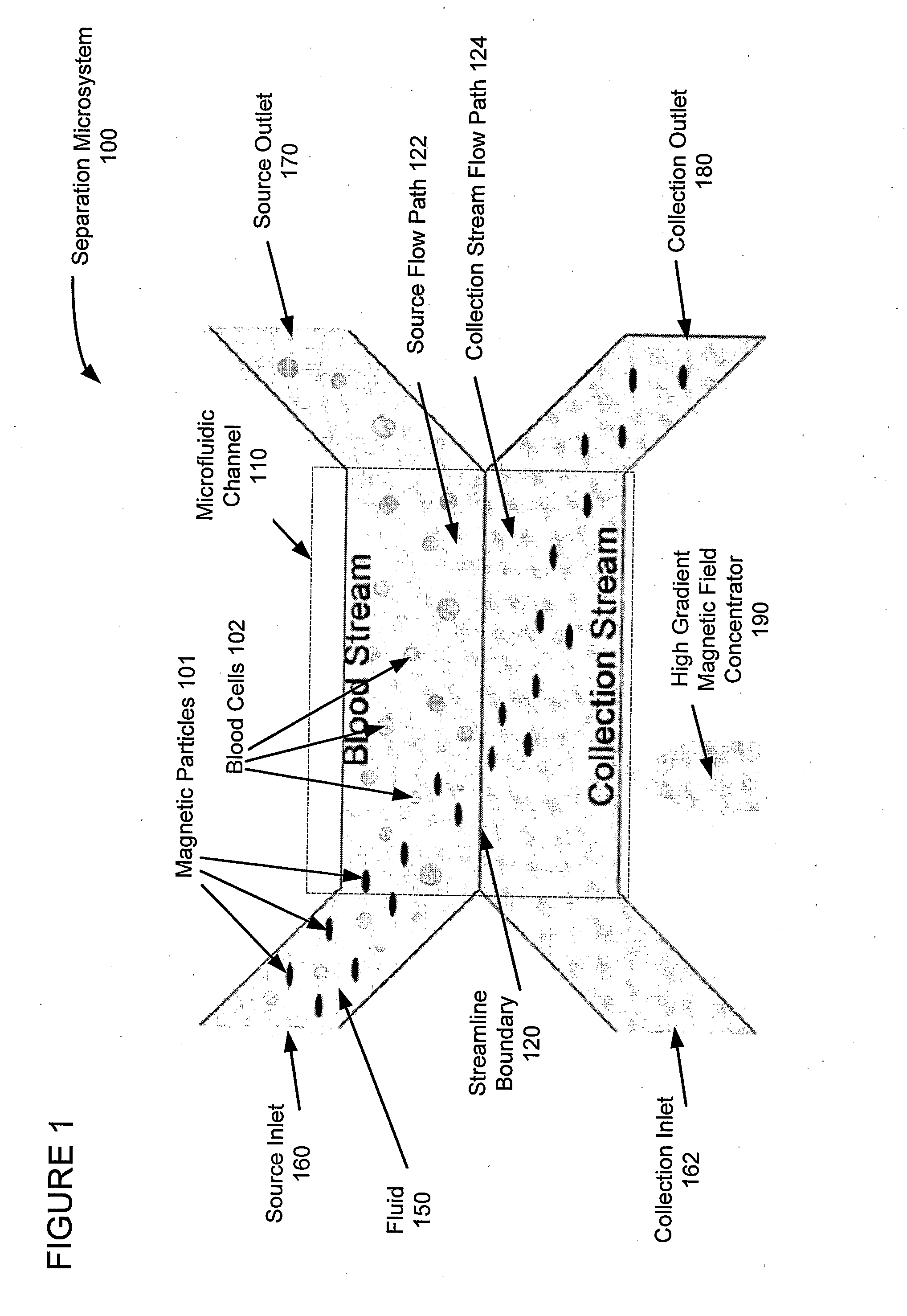
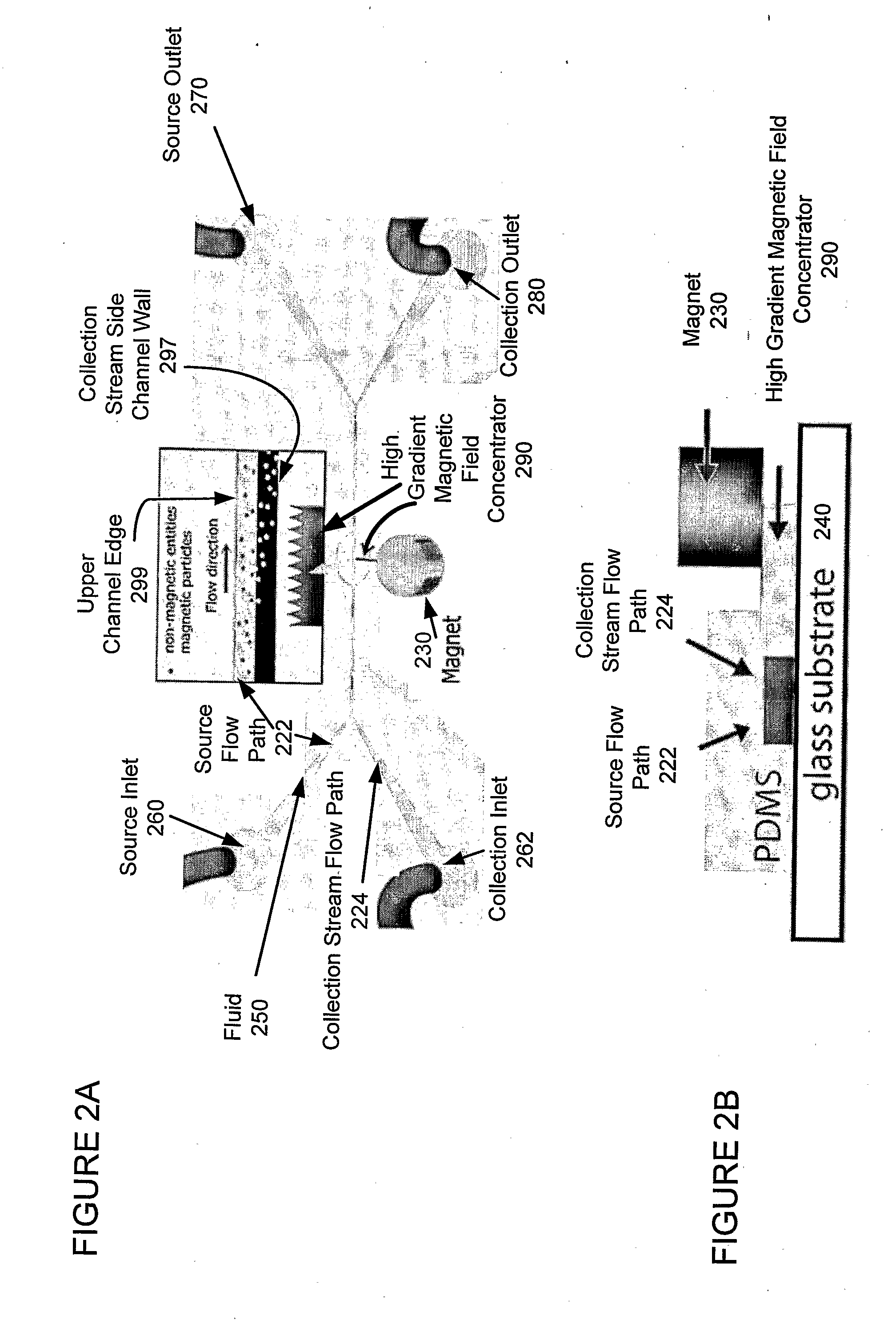
[0016]The present invention extends the functionality of current microfluidic systems techniques to provide on-chip technologies for magnetic separation of living cells from biological fluids such as blood, cerebrospinal fluid, urine, and the like. The present invention combines magnetic and microfluidic separation technologies in continuous flow applications thereby creating effectively unlimited binding and clearance capacity that can be used in portable devices for in-field diagnosis or therapy of diseases, for example, diseases cau...


PUM


Abstract

A miniaturized, integrated, microfluidic device pulls materials bound to magnetic particles from one laminar flow path to another by applying a local magnetic field gradient. The device removes microbial and mammalian cells from flowing biological fluids without any wash steps. A microfabricated high-gradient magnetic field concentrator (HGMC) is integrated at one side of a microfluidic channel. When magnetic particles are introduced into one flow path, they remain limited to that flow path. When the HGMC is magnetized, the magnetic beads are pulled from the initial flow path into the collection stream, thereby cleansing the fluid. The microdevice allows large numbers of beads and materials to be sorted simultaneously, has no capacity limit, does not lose separation efficiency as particles are removed, and is useful for cell separations from blood and other biological fluids. This on-chip separator allows cell separations to be performed in the field outside of hospitals and laboratories.

Description

FIELD OF THE INVENTION[0001]The present invention relates to systems and methods for separating materials from biological fluids. More particularly, it relates to devices and methods for quickly and efficiently separating cells or molecules from biological fluids in a microfluidic channel using a high-gradient magnetic concentrator.BACKGROUND OF THE INVENTION[0002]One of the key functions required for microsystems technologies used for biomedical applications is to separate specific cells or molecules from complex biological mixtures, such as blood, urine, or cerebrospinal fluid. For example, hemofiltration and hemadsorption techniques remove impurities or pathogens in blood. Various physical properties, including size (Huang et al., 2004; Yamada et al., 2004), motility (Cho et al., 2003), electric charge (Lu et al., 2004), electric dipole moment (Fiedler et al., 1998; Hunt et al., 2004), and optical qualities (Fu et al., 1999; Wang et al., 2005), have been studied to separate speci...

Claims


Application Information

Patent Timeline
IPC IPC(8): A01N1/02B01J19/00C12M1/00G01N1/18C12N13/00
CPCA61M1/36A61M2205/0244A61M2206/11B03C1/288B03C2201/26Y10T436/25375G01N15/1463G01N15/1484G01N2015/149A61M1/3618G01N15/1459A61M1/14B01L3/502761B01L2200/0636B01L2200/0668B01L2300/06B01L2300/0864B03C2201/18
Inventor INGBER, DONALD E.XIA, SHANNONHUNT, TOM P.WESTERVELT, ROBERT M.
Owner PRESIDENT & FELLOWS OF HARVARD COLLEGE
Why Eureka
Try Eureka