
Method and system for predicting process performance using material processing tool and sensor data

a technology of process performance and sensor data, applied in the field of material processing, can solve problems such as increasing manufacturing costs, reducing device performance, and material processing in the semiconductor industry

Inactive Publication Date: 2005-11-17
TOKYO ELECTRON LTD
View PDF6 Cites 94 Cited by
  • Summary
  • Abstract
  • Description
  • Claims
  • Application Information

AI Technical Summary

Benefits of technology

The present invention provides a material processing system with a process tool and a process performance prediction system. The system uses sensors to measure tool data and a controller to predict the performance of the process tool based on the data collected from the sensors. The invention also provides a method for predicting the performance of a material processing system by recording tool data and process performance data, performing a matrix multiplication of the data to create a prediction model, and comparing the predicted performance with target performance to detect any faults in the system. The technical effects of the invention include improved process control and optimization, reduced downtime for maintenance, and improved overall performance of the material processing system.

Problems solved by technology

One area of material processing in the semiconductor industry which presents formidable challenges is, for example, the manufacture of integrated circuits (ICs).
However, the etch stop layer complicates the process integration, increases manufacturing cost and decreases device performance.
Since, for example, the etch tool is subject to equipment disturbance, the etch rate can change significantly over maintenance cycles.

Method used


Image

  • Method and system for predicting process performance using material processing tool and sensor data
  • Method and system for predicting process performance using material processing tool and sensor data
  • Method and system for predicting process performance using material processing tool and sensor data

Examples


Embodiment Construction

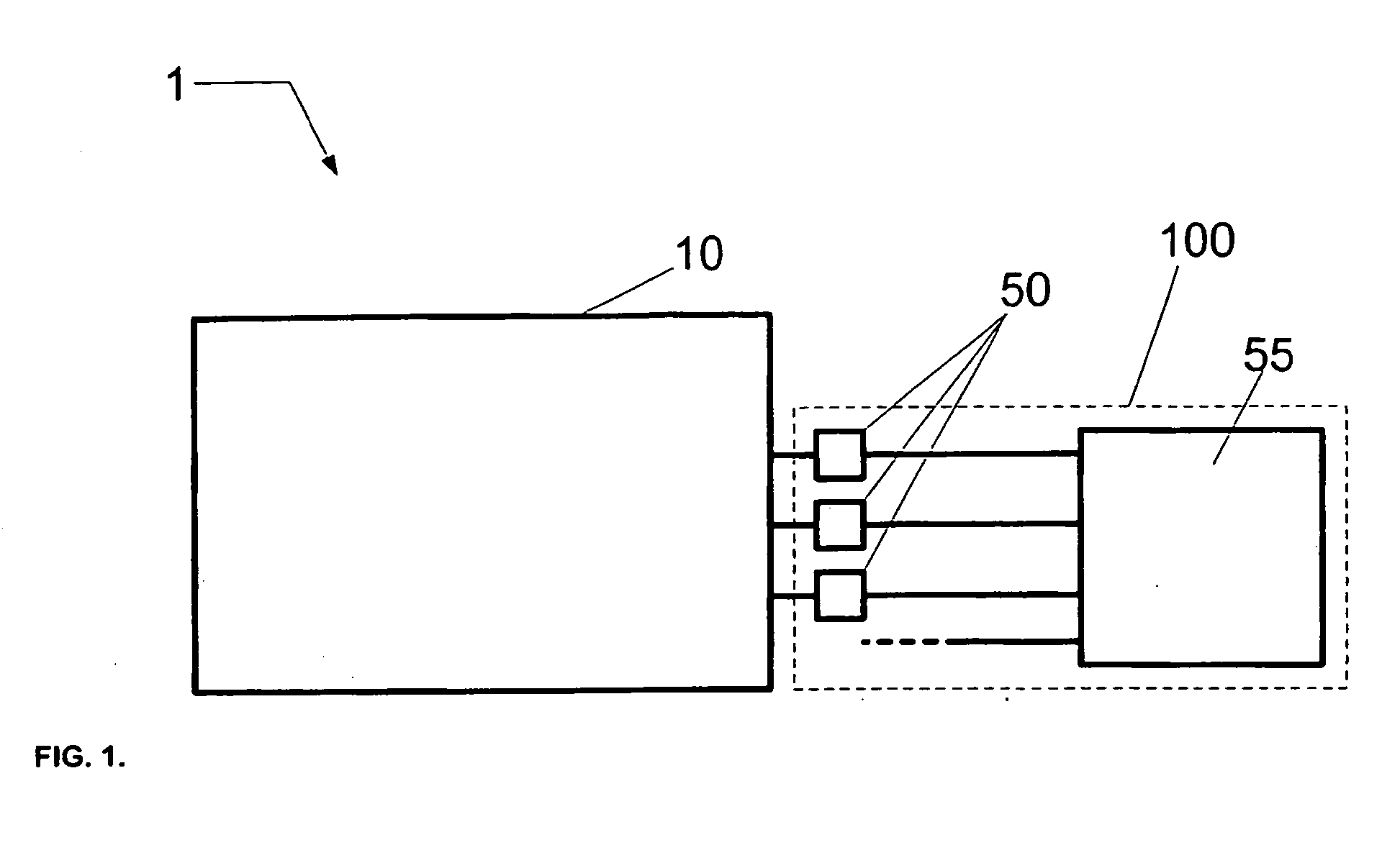
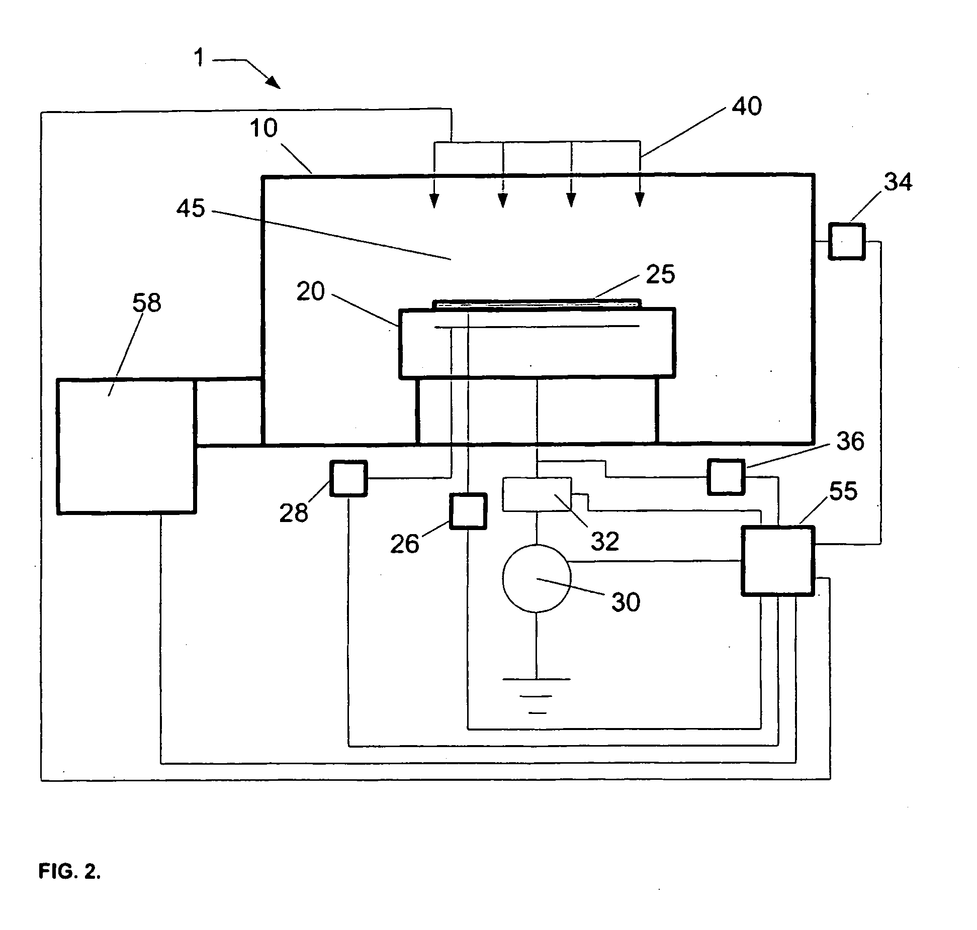
[0029] According to an embodiment of the present invention, a material processing system 1 is depicted in FIG. 1 that includes a process tool 10 and a process performance prediction system 100. The process performance prediction system 100 includes a plurality of sensors 50 and a controller 55. Alternately, the material processing system 1 can include a plurality of process tools 10. The sensors 50 are coupled to the process tool 10 to measure tool data and the controller 55 is coupled to the sensors 50 in order to receive tool data. Alternately, the controller 55 is further coupled to process tool 10. Moreover, the controller 55 is configured to predict process performance data for the process tool using the tool data. The process performance data can include at least one of a process rate and a process uniformity.

[0030] In the illustrated embodiment depicted in FIG. 1, the material processing system 1 utilizes a plasma for material processing. Desirably, the material processing s...


PUM

PropertyMeasurementUnit
sizeaaaaaaaaaa
frequencyaaaaaaaaaa
frequencyaaaaaaaaaa

Abstract

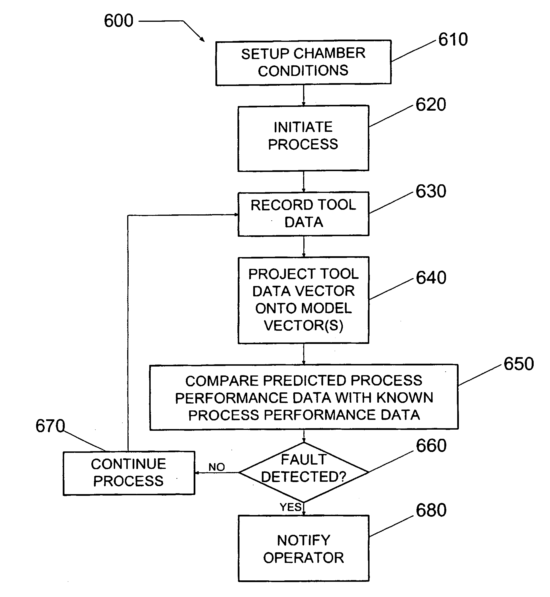
A material processing system including a process tool and a process performance prediction system. The performance prediction system includes sensors coupled to the tool to measure tool data and a controller coupled to the sensors to receive tool data, where the controller is configured to predict the process performance for the tool using the tool data. A method for detecting a fault in a material processing system using a process performance prediction model is also provided. The method includes preparing the tool, initiating a process in the tool, and recording tool data to form to a tool data matrix. The method also includes performing a matrix multiplication of the tool data matrix and a correlation matrix to form predicted process performance data, where the correlation matrix includes the performance prediction model, comparing the predicted data with target data, and determining a fault condition of the processing system from the comparing step.

Description

CROSS-REFERENCE TO RELATED APPLICATIONS [0001] The present application claims priority to previously filed U.S. Application Ser. No. 60 / 391,965, filed on Jun. 28, 2002. This application is related to U.S. Application Ser. No. 60 / 391,966, filed on Jun. 28, 2002. The entire contents of these applications are incorporated herein by reference.FIELD OF THE INVENTION [0002] The present invention relates to material processing and more particularly to a process performance prediction system and method thereof for predicting process performance including process rate and process uniformity. BACKGROUND OF THE INVENTION [0003] One area of material processing in the semiconductor industry which presents formidable challenges is, for example, the manufacture of integrated circuits (ICs). Demands for increasing the speed of ICs in general, and memory devices in particular, force semiconductor manufacturers to make devices smaller and smaller on the substrate surface. Moreover, in order to reduce...

Claims


Application Information

Patent Timeline
Patent Type & Authority Applications(United States)
IPC IPC(8): H01L21/3065C23F1/00G05B19/418G05B23/02H01L21/66
CPCG05B19/41875G05B23/0254G05B2219/31357G05B2219/32179H01L22/20G05B2219/45028G05B2219/45031H01J37/32935G05B2219/32194Y02P90/02
Inventor LAM, HIEU A.YUE, HONGYUSHRINER, JOHN
Owner TOKYO ELECTRON LTD
Learn More