Unwinding apparatus for reeling off coiled material

a technology of unwinding apparatus and coiled material, which is applied in the direction of filament handling, web handling, magazine/cassette storage, etc., can solve the problems of large space for transport and storage, difficult handling of coils, and limited use of annular coils of different inner and outer diameters, etc., to achieve convenient transportation and storage, the effect of easy conversion

Active Publication Date: 2005-11-17
BOHNISCH RUDOLF
View PDF16 Cites 21 Cited by
  • Summary
  • Abstract
  • Description
  • Claims
  • Application Information

AI Technical Summary

Benefits of technology

[0016] The swingable arms of the take-up device and the stand can be pivoted to the respectively fixed arms thereof and their extensions are telescopically moved inside and secured. The arms of the take-up device and the stand are aligned in coaxial relationship to thereby establish a narrow, compact configuration that can easily be transported and stored. The brake unit is activated to restrain the take-up device against rotation relative to the stand during transport.

Problems solved by technology

Not only because of their extensive length but also because of their great weight, these coils are difficult to handle.
A drawback of prior art unwinding devices is their limited use to accommodate annular coils of different inner and outer diameters, different heights and different weights, and their bulky and heavy construction that requires large spaces for their transport and storage.
As a result, the length of unwound material is longer than desired so that a portion of material dangles from the take-up device and may get entangled in the apparatus.
Thus, the subsequent unwinding operati

Method used


Image

  • Unwinding apparatus for reeling off coiled material
  • Unwinding apparatus for reeling off coiled material
  • Unwinding apparatus for reeling off coiled material

Examples


Embodiment Construction

[0033] Throughout all the Figures, same or corresponding elements are generally indicated by same reference numerals. These depicted embodiments are to be understood as illustrative of the invention and not as limiting in any way. It should also be understood that the drawings are not necessarily to scale and that the embodiments are sometimes illustrated by graphic symbols, phantom lines, diagrammatic representations and fragmentary views. In certain instances, details which are not necessary for an understanding of the present invention or which render other details difficult to perceive may have been omitted.

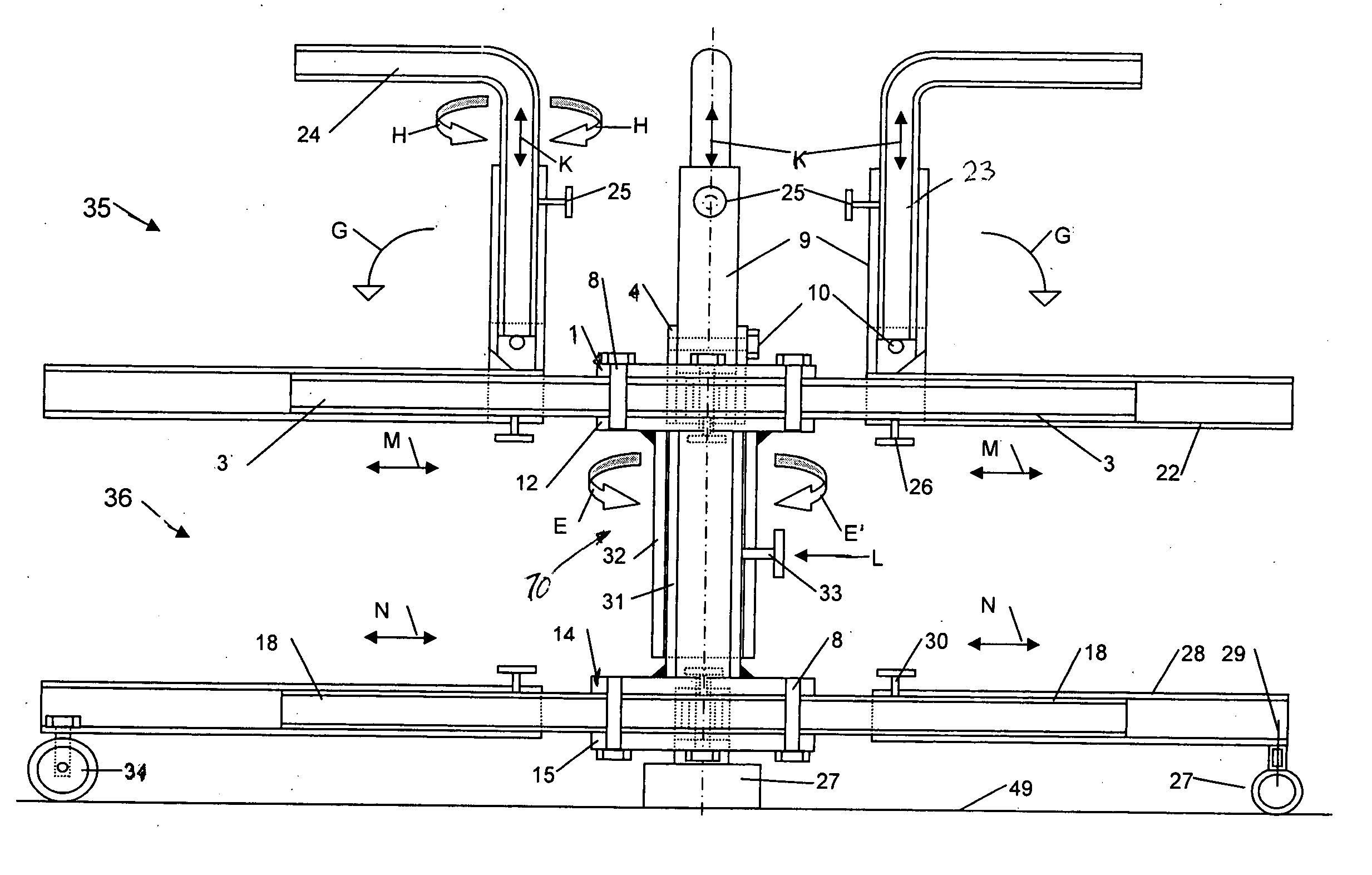
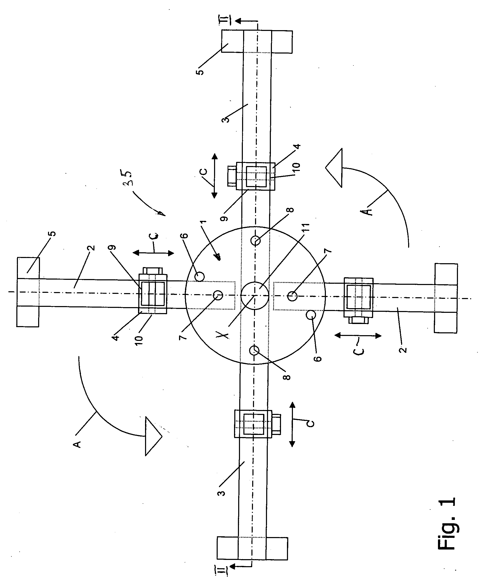
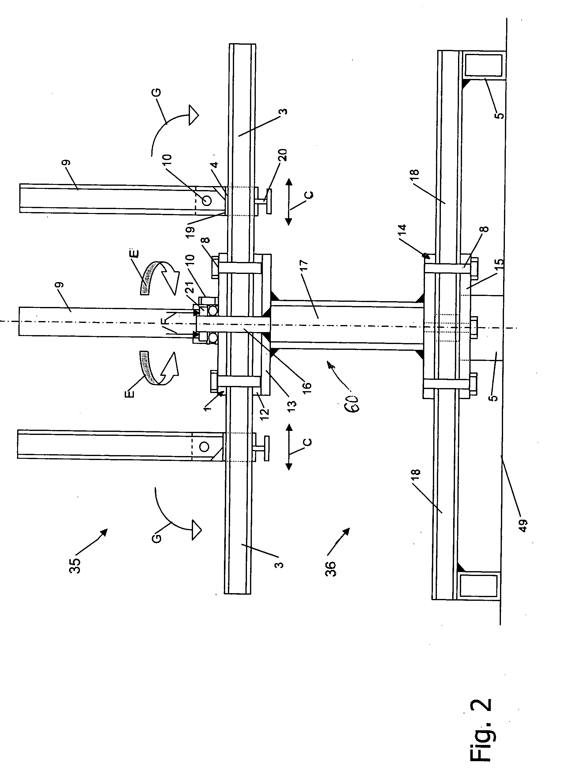
[0034] Turning now to the drawing, and in particular to FIG. 1, there is shown a schematic plan view of one embodiment of an unwinding apparatus according to the present invention, including a take-up device, generally designated by reference numeral 35 and provided for paying out by hand coiled material 39 in the form of annular coils 38, as the take-up device 35 rotates ab...


PUM


Abstract

An unwinding apparatus for reeling off coiled material includes a take-up device for supporting the coiled material. The take-up device has a plurality of spaced-apart arms extending radially in a plane, with at least one of the arms swingably mounted in the plane. Swingably mounted to at least one of the arms is a centering pin so that the centering pin extends in a transport position in parallel relationship to the arm.

Description

CROSS-REFERENCES TO RELATED APPLICATIONS [0001] This application claims the priority of German Patent Application, Serial No. 10 2004 016 658.7, filed Apr. 5, 2004, pursuant to 35 U.S.C. 119(a)-(d), the subject matter of which is hereby incorporated by reference. BACKGROUND OF THE INVENTION [0002] The present invention relates to an unwinding apparatus for reeling off coiled material such as cables or annular pipes or similar winding goods, such as plastic tubes (used, e.g., for installation of water pipelines or heating pipelines), that have been wound to annular coils. [0003] Electric cables or pipes, for example for a floor heating system, are oftentimes very long, e.g. of 50 m to 750 m, and thus wound into annular coils. Typically, the coiled material has a hardness that allows elastic bending. Not only because of their extensive length but also because of their great weight, these coils are difficult to handle. Thus, unwinding devices are used for processing the annular coils a...

Claims


Application Information

Patent Timeline
IPC IPC(8): B65H49/28B65H49/30
CPCB65H49/305B65H49/30
Inventor BOHNISCH, RUDOLF
Owner BOHNISCH RUDOLF
Why Eureka
Try Eureka