Traffic radar system with improved patrol speed capture

a technology of traffic radar and speed capture, applied in the field of traffic radar system, can solve the problems of system not reducing initial patrol search errors, difficult radar system detection, and inability of police departments to easily access the wiring of speedometers, etc., and achieve the effect of improving patrol speed captur

Inactive Publication Date: 2005-11-17
KUSTOM SIGNALS
View PDF16 Cites 7 Cited by
  • Summary
  • Abstract
  • Description
  • Claims
  • Application Information

AI Technical Summary

Benefits of technology

[0009] The present invention improves patrol speed capturing in the absence of a speedometer input. The system can search for the patrol return sig

Problems solved by technology

Since there may only be a slight difference between a combined signal and a patrol vehicle signal pattern, it may be difficult for the radar system to discern.
One limitation of this and other systems with a speedometer

Method used


Image

  • Traffic radar system with improved patrol speed capture
  • Traffic radar system with improved patrol speed capture
  • Traffic radar system with improved patrol speed capture

Examples


Embodiment Construction

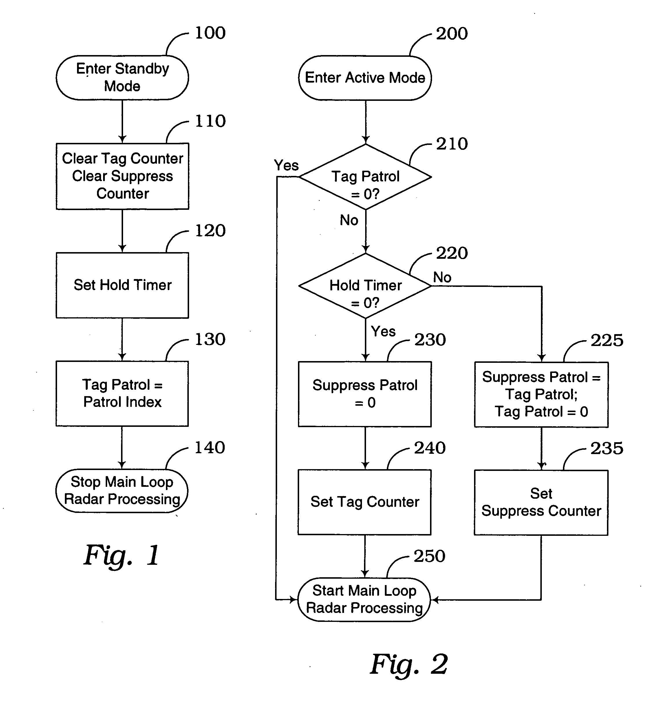
[0013] In a traffic radar system, after the system is turned on, the operator places the system in an inactive state often referred to as a standby or a hold mode so that the system is not transmitting. This helps reduce the early detection of the traffic radar transmission by radar detectors in motor vehicles of potential speeders. When the officer wants to obtain the speed of a target vehicle, the officer switches the radar unit to an active transmitting state. If the patrol vehicle is moving, the system first determines the patrol vehicle signal and associated speed and then determines the target vehicle signal and associated speed from all of the return signals. If the target vehicle is traveling in a direction opposite to the direction of the patrol vehicle, the patrol speed is subtracted from the combined speed of the patrol vehicle and the target vehicle to determine the target vehicle speed for display.

[0014] When using the radar system in the moving mode, typically the ope...


PUM


Abstract

A traffic radar captures the patrol vehicle return signal by saving the patrol return when the radar system is placed in a standby state. If the radar is in standby for more than a predetermined period of time before reentering a transmitting mode, the system searches for a new patrol signal within a speed window around the saved patrol signal speed. If the radar is in standby for less than the predetermined period of time, the system initially searches for a new patrol signal over a range that excludes an interval around the saved patrol signal speed. If the new patrol signal is not found, then in a subsequent search the interval is included in the searched spectrum.

Description

CROSS REFERENCE TO RELATED APPLICATIONS [0001] This application claims the benefit of prior filed, co-pending Ser. No. 60 / 571,350, filed May 14, 2004, entitled TRAFFIC RADAR SYSTEM WITH IMPROVED PATROL SPEED CAPTURE.FIELD OF THE INVENTION [0002] The present invention relates to a traffic radar system and, in particular, to a traffic radar system which utilizes an improved algorithm to determine and capture the patrol vehicle speed. BACKGROUND OF THE INVENTION [0003] Traffic radar systems are widely used in law enforcement. Since the introduction of the first moving radar system, there have been anomalies known as combining and shadowing. Combining may occur when the combined patrol car return signal and oncoming target's return signal is of greater strength than the actual patrol car return signal. Since there may only be a slight difference between a combined signal and a patrol vehicle signal pattern, it may be difficult for the radar system to discern. As a result, if a police of...

Claims


Application Information

Patent Timeline
IPC IPC(8): G01S7/40G01S13/58G01S13/92
CPCG01S13/92G01S7/4021
Inventor SHELTON, MAURICE E.HOCKER, STEVEN F.
Owner KUSTOM SIGNALS
Why Eureka
Try Eureka