Tiled displays and methods for driving same

a technology of electrooptic displays and tiles, applied in the field of tiles, can solve the problems of preventing their widespread use, inadequate service life of these displays, and gas-based electrophoretic media being susceptible to the same types of problems, so as to reduce the variation in electrooptic performance

Inactive Publication Date: 2005-11-17
E INK CORPORATION +1
View PDF99 Cites 454 Cited by
  • Summary
  • Abstract
  • Description
  • Claims
  • Application Information

AI Technical Summary

Benefits of technology

[0021] Accordingly, in one aspect, this invention provides a tiled electro-optic display comprising a plurality of display units each of which can be individually removed from the display, and a controller arranged to supply drive signals to the plurality of display units and thereby write images thereon, the electro-optic display further comprising means for modifying the drive signals supplied by the controller to reduce variation in electro-optic performance among the plurality of display units.

Problems solved by technology

Nevertheless, problems with the long-term image quality of these displays have prevented their widespread usage.
For example, particles that make up electrophoretic displays tend to settle, resulting in inadequate service-life for these displays.
Such gas-based (“GB”) electrophoretic media appear to be susceptible to the same types of problems due to particle settling as liquid-based electrophoretic media, when the media are used in an orientation which permits such settling, for example in a sign where the medium is disposed in a vertical plane.
Such large area displays typically have a complex hierarchy of physical elements, signals and controllers.
However, maintaining consistent electro-optic properties within a large area display, comprising individually replaceable tiles, presents problems.
Adjusting the performance of individual tiles (of which there may be 100 or more) to account for these factors would be an extremely complex task for the central controller.

Method used


Image

  • Tiled displays and methods for driving same
  • Tiled displays and methods for driving same

Examples


Embodiment Construction

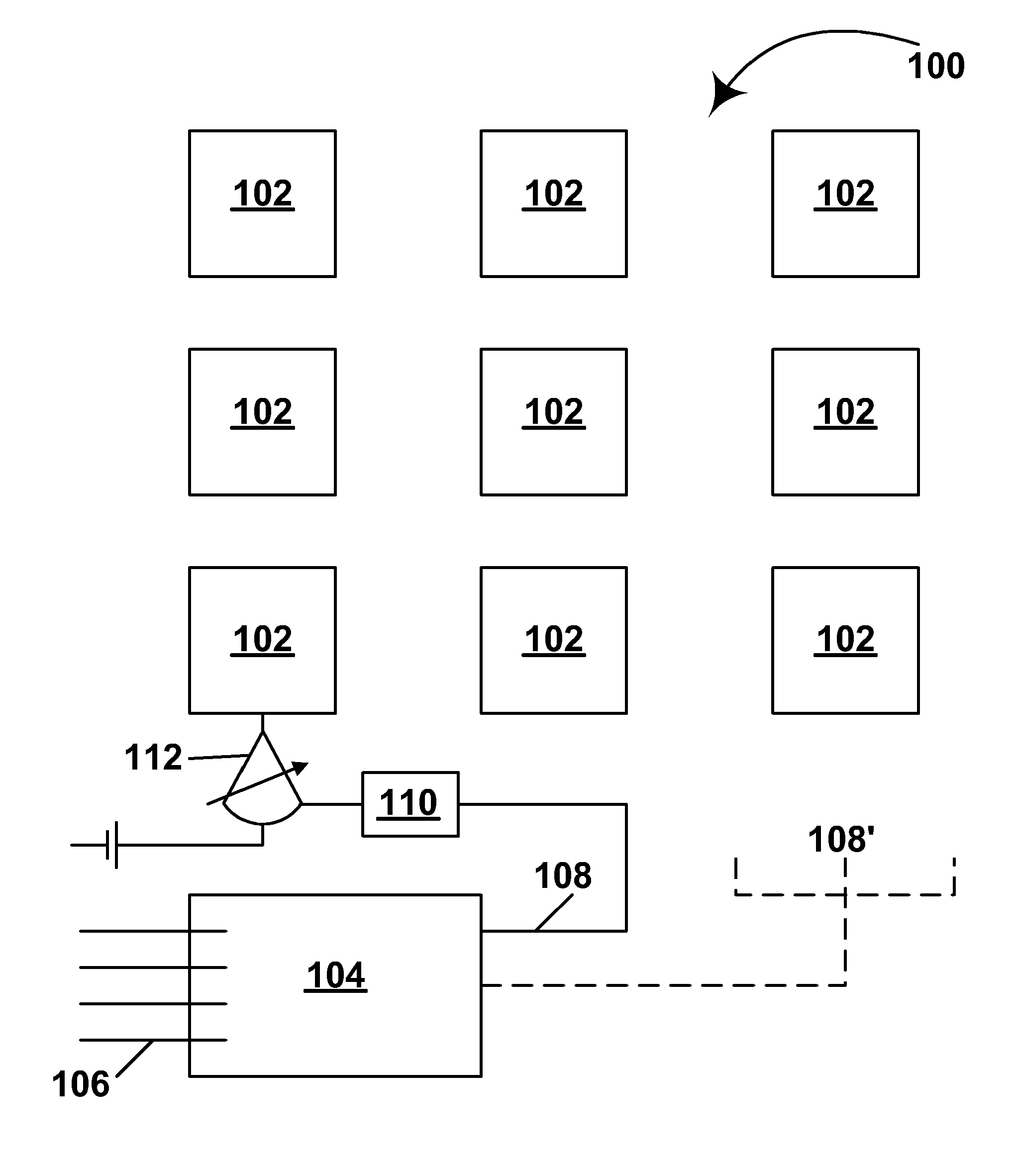
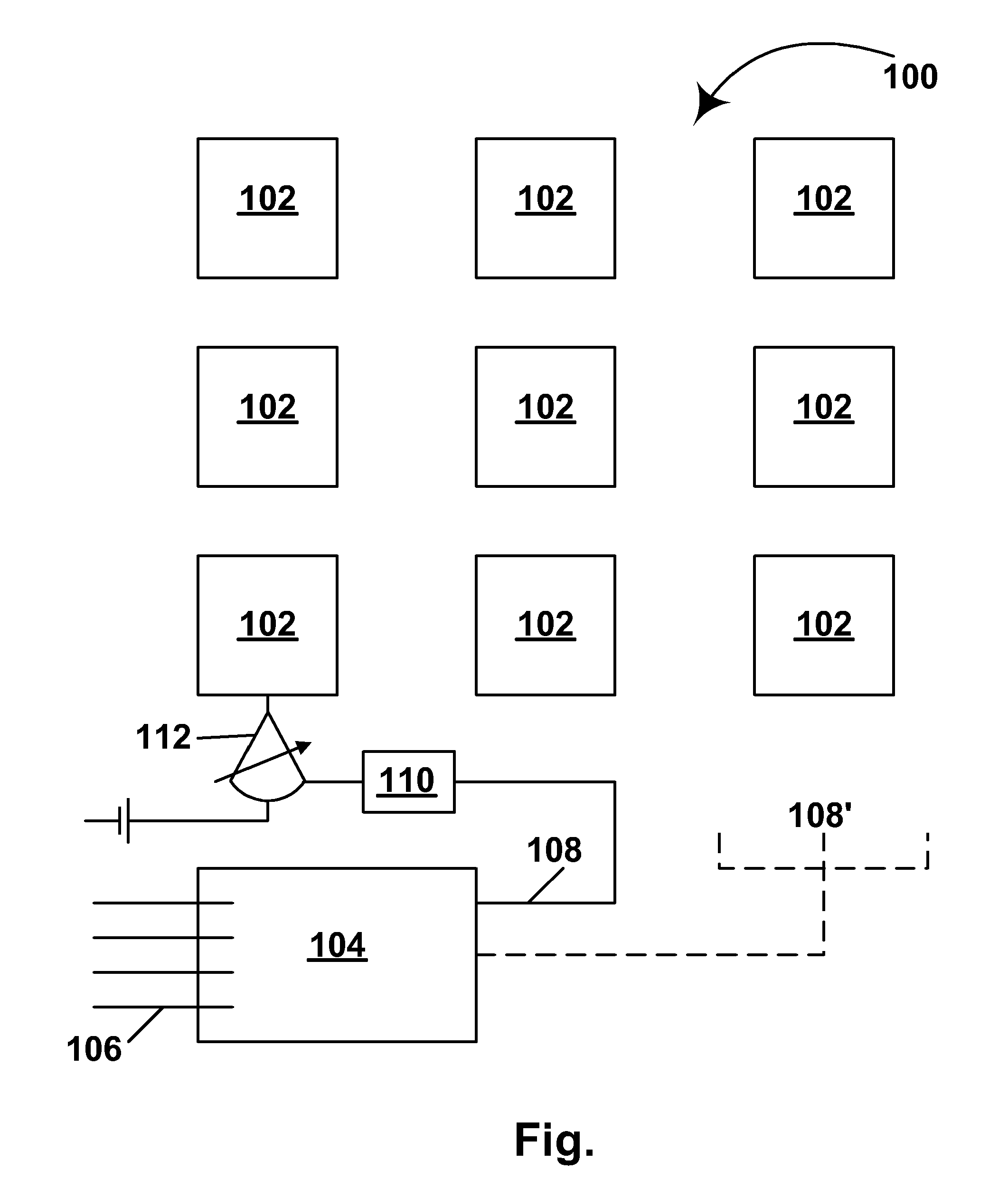
[0028] As already indicated, the present invention relates to modifying the drive signals supplied by a controller to the various display units (“tiles”) of a tiled electro-optic display in order to reduce variation in electro-optic performance among the display units. The modification of the drive signals can be effected in several different ways, and optionally the tiled electro-optic display may include means for further adjusting the drive signals to take account of environmental or other parameters which affect the electro-optic performance of the display.

[0029] In one aspect, this invention provides for the drive voltages supplied to each tile to be modified to reduce variation in electro-optic performance among tiles. The drive voltages may be adjusted by, for example, inserting operational amplifiers with adjustable gain (preferably with a gain less than or equal to 1) between power supplies and the individual tile inputs, so that the actual voltage applied to a given tile ...


PUM


Abstract

A tiled electro-optic display ( 100 ) comprises a plurality of display units ( 102 ) each of which can be individually removed from the display, and a controller ( 104, 110 ) arranged to supply drive signals to the plurality of display units ( 102 ) and thereby write images thereon, the electro-optic display ( 100 ) further comprising means ( 112 ) for modifying the drive signals supplied by the controller ( 104, 110 ) to reduce variation in electro-optic performance among the plurality of display units ( 102 ).

Description

REFERENCE TO RELATED APPLICATIONS [0001] This application claims benefit of Provisional Application Ser. No. 60 / 570,254 filed May 12, 2004. The entire disclosure of this application, and of all U.S. patents and published and copending applications mentioned below, are herein incorporated by reference.BACKGROUND OF INVENTION [0002] This invention relates to tiled displays, more specifically tiled electro-optic displays, and to methods for driving such displays. [0003] The term “tiled displays” is used herein to refer to displays which are formed from a plurality of sub-units at least some of which can be replaced individually. The term does not imply that all the sub-units in such a display are identical, although obviously it is often convenient to use such identical sub-units. [0004] Electro-optic displays comprise a layer of electro-optic material, a term which is used herein in its conventional meaning in the art to refer to a material having first and second display states diffe...

Claims


Application Information

Patent Timeline
Patent Type & Authority Applications(United States)
IPC IPC(8): G06F3/14G09G3/34G09G5/00
CPCG06F3/1446G09G3/34G09G3/344G09G2300/026G09G2320/0233G09G2360/145G09G2320/041G09G2320/043G09G2320/048G09G2320/0626G09G2320/0285
Inventor ZEHNER, ROBERT W.MALCHEREK, WERNER
Owner E INK CORPORATION
Why Eureka
Try Eureka