Separation method and assembly for process streams in component separation units

Active Publication Date: 2005-11-17
CRYSTAPHASE PRODS
View PDF22 Cites 26 Cited by
  • Summary
  • Abstract
  • Description
  • Claims
  • Application Information

AI Technical Summary

Benefits of technology

[0050] The methods and assemblies of the present invention for separating one or more process streams into component process streams having desired compositions using CELLDIST materials in a component separation unit, when compared with prior art

Problems solved by technology

Contaminants in process streams can be deleterious to processes and also to process units.
Contaminants can damage process units, potentially resulting in an environmental or safety incident.
Contaminants can also damage processes by decreasing efficiencies within processes, stopping production, affecting the specifications of products, or the like.
Such catalyst beds, however, can quickly become clogged by these trapped contaminants.
As the bed becomes clogged, pressure drop across the process unit rises resulting in eventual premature shutdown of the process unit.
While these conventional retention material beds can be somewhat effective in preventing the process unit from being clogged, the conventional retention material beds themselves eventually become clogged.
Conventional retention material beds exposed to contaminants at the inlet to a process unit will eventually become clogged with contaminants.
As this happens, the pressure drop across the process unit rises, resulting in the eventual shutdown of the unit.
When this happens in catalyst bed process units, it is typical that part of the catalyst bed itself becomes somewhat or completely clogged with contaminants.
In addition to clogging by contaminants in the process stream, polymerization of polymer precursors, e.g., diolefins, found in the process streams fed to catalyst bed process units may also foul, gum or plug such process units.
In particular, two mechanisms of polymerization, free radical polymerization and condensation-type polymerization, may cause catalyst bed fouling, gumming or plugging.
Therefore, filtering prior to the process stream entering the catalyst bed process unit may not be helpful to remove these foulants as the polymerization reactions generally take place in the unit.
Weaknesses of conventional retention material beds are that they are neither particularly efficient nor particularly effective as filters.
The effectiveness of conventional retent

Method used


Image

  • Separation method and assembly for process streams in component separation units
  • Separation method and assembly for process streams in component separation units
  • Separation method and assembly for process streams in component separation units

Examples


Example

EXAMPLE 1

Use in a Distillate Hydrotreater

[0084] Data were obtained from a refinery for four distillate hydrotreaters in virtually identical process conditions. Two of the hydrotreaters, A and B, contained conventional reticulated materials, known as “ring grading systems.” The remaining two hydrotreaters, C and D, used the reticulated elements of the present invention. FIG. 17 shows a comparison of the pressure drop of the four hydrotreaters using conventional ring grading systems and the reticulated elements of the present invention. As can be seen in the graph, the pressure drop remained low relative to start-of-run pressure drop over a period in excess of 450 days in the C and D hydrotreaters containing the reticulated elements, while the A and B hydrotreaters using the conventional ring grading system showed a dramatic pressure increase after only 200 days in service. The results of the pressure drop comparison can be seen in Table 1. The contaminated process streams in the di...

Example

EXAMPLE 2

Use in a Naphtha Hydrotreater

[0086] Data was obtained from a refinery with four naphtha hydrotreaters. Three of the hydrotreaters (A, B, and C) used conventional ring grading systems, while the remaining hydrotreater (D) used the reticulated elements of the present invention. FIG. 18 illustrates that comparative pressure drop between the four hydrotreaters. At the end of 200 days, the unit with the reticulated elements D experienced minimal pressure drop, i.e. −4 psi for hydrotreater D, compared to the pressure drop experienced by the three units containing ring grading systems, i.e. 10 psi for hydrotreater B and 22 psi for hydrotreater C. The contaminated process streams in the naphtha hydrotreaters were predominantly in a vapor phase. The reticulated elements of the present invention filtered efficiently and effectively while the conventional ring grading systems became clogged.

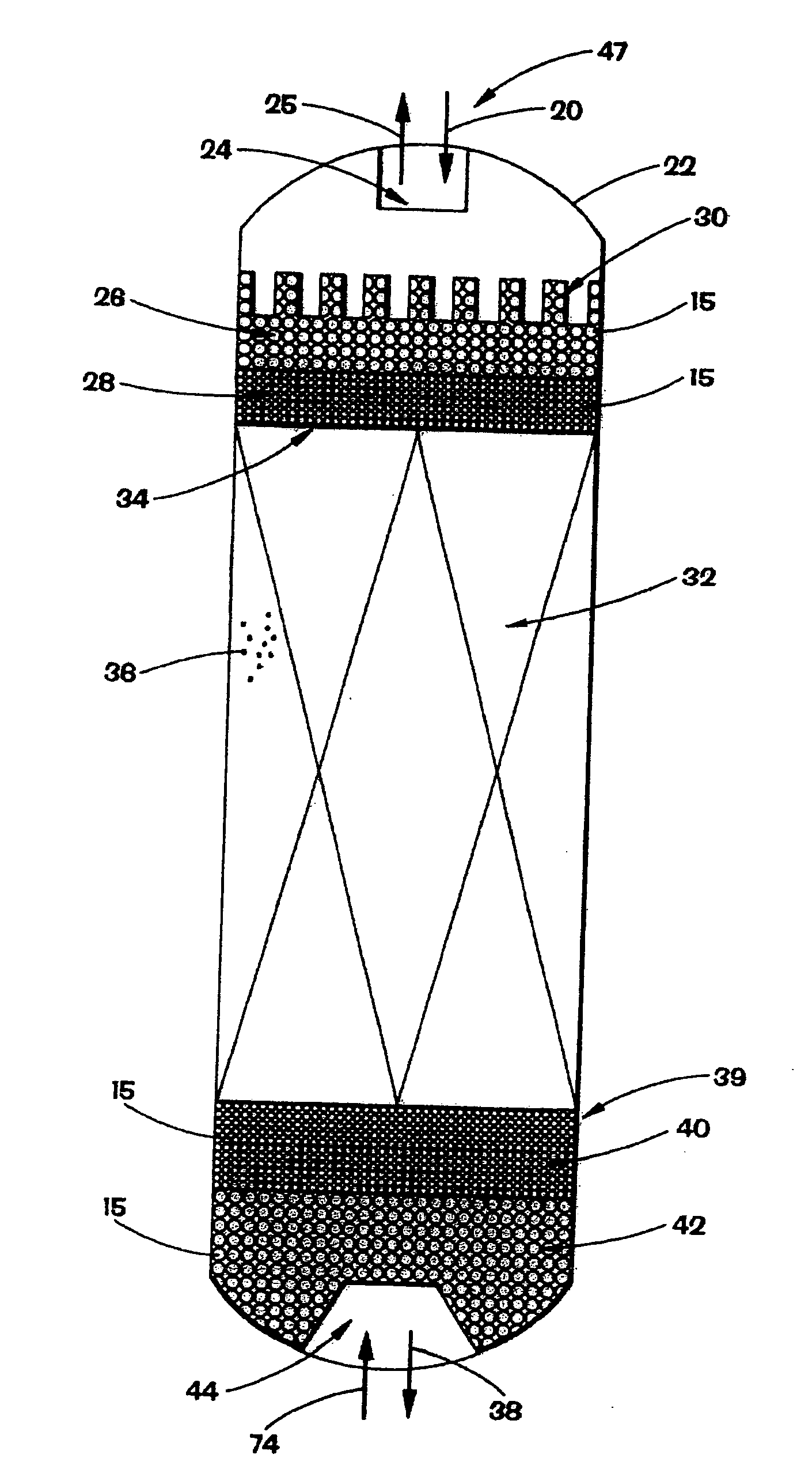
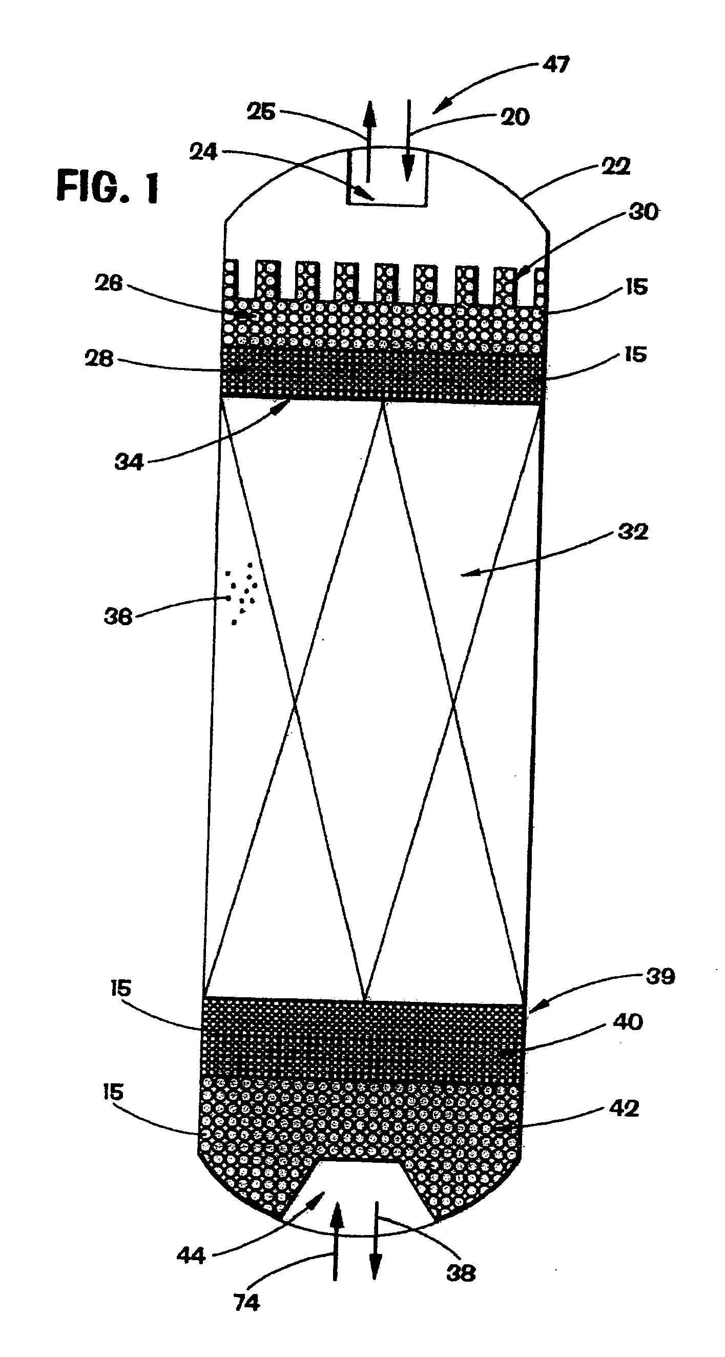
[0087] Referring again to FIG. 1, unless otherwise noted, in addition to filtering the conta...


PUM

PropertyMeasurementUnit
Surface areaaaaaaaaaaa
Compositionaaaaaaaaaa
Sizeaaaaaaaaaa

Abstract

A method and assembly for utilizing open-cell cellular solid material in a component separation unit to separate one or more process streams into component process streams having desired compositions. A method and assembly for using said open-cell cellular solid material to separate process streams into desired component process streams in a component separation unit, wherein the open-cell cellular solid material can include oxides, carbides, nitrides, borides, ceramics, metals, polymers, and chemical vapor deposition materials.

Description

RELATED APPLICATION [0001] This application is a continuation-in-part of U.S. patent application Ser. No. 10 / 396,851, filed on Mar. 25, 2003.BACKGROUND OF THE INVENTION [0002] 1. Field of the Invention [0003] The invention relates to a method of providing filtration of contaminants from process streams. In another aspect, this invention relates to a method for providing flow distribution of process streams in process units. In yet another aspect, this invention provides filtration or flow distribution or both while concurrently catalyzing at least one reaction to at least partially remove and / or convert certain chemical species within the process stream. In yet another aspect, this invention relates to a method and assembly for utilizing at least one cellular solid material in a component separation unit to separate one or more process streams into one or more component process streams having desired compositions. [0004] 2. Description of Related Art [0005] Contaminants in process s...

Claims


Application Information

Patent Timeline
IPC IPC(8): B01D3/14B01D3/16B01D39/06B01D46/00B01D53/86B01J8/04B01J8/26B01J19/30B01J23/85C08F2/00
CPCB01D3/009C10G25/003B01D3/16B01D3/38B01D39/06B01D39/2051B01D39/2093B01D46/10B01D53/02B01D53/0423B01D53/86B01D2253/106B01D2253/112B01D2253/202B01D2253/306B01D2253/311B01D2253/342B01D2259/41B01D2275/40B01J8/006B01J8/0085B01J8/009B01J8/0214B01J8/0453B01J8/0469B01J8/0492B01J8/26B01J19/2485B01J19/30B01J19/305B01J23/85B01J35/04B01J2208/025B01J2219/00247B01J2219/00252B01J2219/30203B01J2219/30207B01J2219/30215B01J2219/30219B01J2219/30223B01J2219/30246B01J2219/30257B01J2219/30276B01J2219/30408B01J2219/30416B01J2219/30475B01J2219/3083B01J2219/3085B01J2219/32279C10G7/00C10G21/00B01D3/14B01D53/04B01J12/00
Inventor GLOVER, JOHN N.HAM, PETER G.RAO, KRISHNA K.MCGOVERN, STEPHEN J.
Owner CRYSTAPHASE PRODS
Why Eureka
Try Eureka