Heart valve annuloplasty prosthesis sewing cuffs and methods of making same

Active Publication Date: 2005-11-17
ST JUDE MEDICAL LLC
View PDF66 Cites 169 Cited by
  • Summary
  • Abstract
  • Description
  • Claims
  • Application Information

AI Technical Summary

Benefits of technology

[0004] To facilitate suturing an annuloplasty prosthesis into a patient, a sewing cuff is added to the prosthesis in accordance with the invention. Such a sewing cuff is preferably an extension of the fabric cover that is provided around the core of the prosthesis. The sewing cuff preferably extends radially outwardly from cross sections of the core and the remainder of the fabric cover. Stitching may be used to stabilize the extension. The extension may be one

Problems solved by technology

The core member is often substantially rigid or at least semi-rigid and not penetrable by a suture needle and suture material.
Tightness and/or thinness of the fabric cover may make this

Method used


Image

  • Heart valve annuloplasty prosthesis sewing cuffs and methods of making same
  • Heart valve annuloplasty prosthesis sewing cuffs and methods of making same
  • Heart valve annuloplasty prosthesis sewing cuffs and methods of making same

Examples


Embodiment Construction

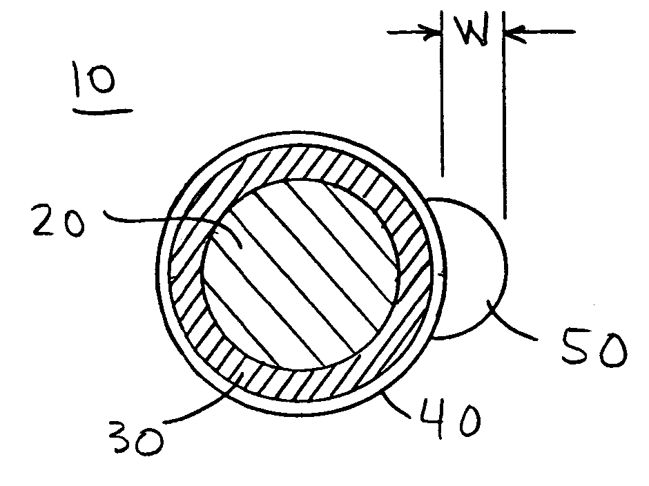
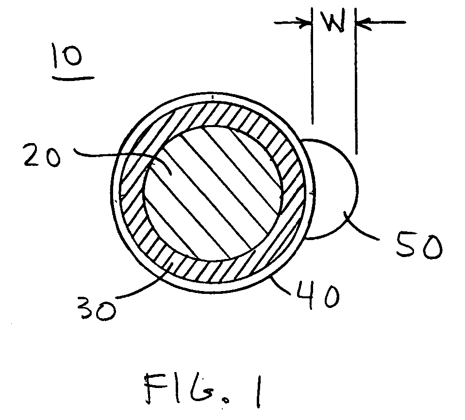
[0017] The annuloplasty prosthesis 10 cross section shown in FIG. 1 includes core member 20, a layer 30 of an elastomeric material surrounding core 20, and fabric cover 40 surrounding elements 20 and 30. FIG. 1 also shows what may be described as a mini-sewing-cuff 50 extending radially outwardly from the other elements at one angular location or region around the circumference of the cross section. For completeness FIG. 7 shows a plan view of an entire illustrative annuloplasty prosthesis 10 in accordance with the invention and which can have a cross section as shown in FIG. 1 (or as in other FIGS. subsequent to FIG. 1). Although FIG. 7 shows the cross section taken at one particular location, substantially the same cross section may be found at other (or even all) locations annularly around prosthesis 10. Also, although FIG. 7 shows a prosthesis 10 that is a complete, unbroken, generally D-shaped annulus, prosthesis 10 could have other shapes, and could alternatively be only a por...


PUM


Abstract

An annuloplasty prosthesis for a heart valve has a sewing cuff added to the conventional structure. The sewing cuff is preferably an extension of the fabric cover that is provided around the core of the prosthesis. The sewing cuff preferably extends radially outwardly from cross sections of the remainder of the prosthesis. Methods of making such a sewing cuff are also disclosed.

Description

[0001] This application claims the benefit of U.S. provisional patent application No. 60 / 571,437, filed May 14, 2004, which is hereby incorporated by reference herein in its entirety.BACKGROUND OF THE INVENTION [0002] Annuloplasty prostheses for heart valves are well known as is shown, for example, by Alfieri et al. U.S. patent application publication US 2002 / 0173844 Al and Bolling et al. U.S. patent application publication US 2003 / 0093148 Al. Such prostheses may be complete rings (e.g., as in the above-mentioned Alfieri et al. and Bolling et al. references), or they may be less than complete rings (e.g., as in Carpentier U.S. patent 3,656,185). The term “annuloplasty” is used herein to refer to both of these types of prostheses (i.e., both complete rings and less than completely annular structures (e.g., generally C-shaped structures)). [0003] Typical annuloplasty prostheses include a core member surrounded by a soft fabric cover. The core member is often substantially rigid or at ...

Claims


Application Information

Patent Timeline
IPC IPC(8): A61F2/24
CPCA61F2/2448A61F2/2409A61F2/2442A61F2/2445
Inventor LIM, JYUE BOONMCCARTHY, ANDREA L.
Owner ST JUDE MEDICAL LLC
Why Eureka
Try Eureka