Image-processing apparatus

a technology of image processing and apparatus, applied in the field of image processing apparatus, can solve the problems of cumbersome operation, cumbersome operation, and the inability of the operation unit to handle the high volume of information to be displayed on the display unit, and achieve the effect of high volume of data, easy selection, and rapid reading ou

Inactive Publication Date: 2005-11-24
ALPS ALPINE CO LTD
View PDF9 Cites 19 Cited by
  • Summary
  • Abstract
  • Description
  • Claims
  • Application Information

AI Technical Summary

Benefits of technology

[0024] In the present invention, a high volume of data can be easily selected, and the selected main data can be quickly read out.

Problems solved by technology

Unfortunately, since known input devices are mainly numeric keypads or keyboards, operation units cannot handle the high volume of information to be displayed on display units.
Thus, for example, a user needs to press buttons provided on a remote controller many times to display necessary information, and the operation thus becomes cumbersome.
However, even when this input device is used in combination with a display unit for displaying a high volume of information, the user needs to sequentially display multiple screens by performing a predetermined operation.
Thus, when the user selects any information from the high volume of information, the operation is cumbersome.

Method used


Image

  • Image-processing apparatus
  • Image-processing apparatus
  • Image-processing apparatus

Examples


first embodiment

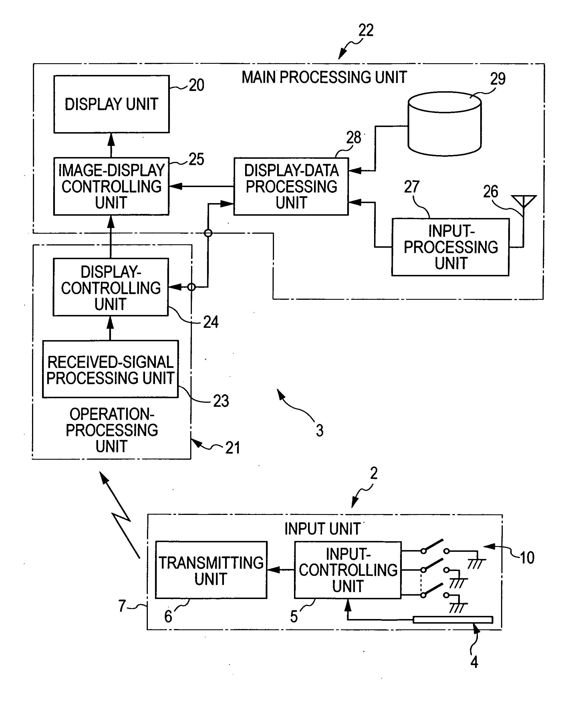
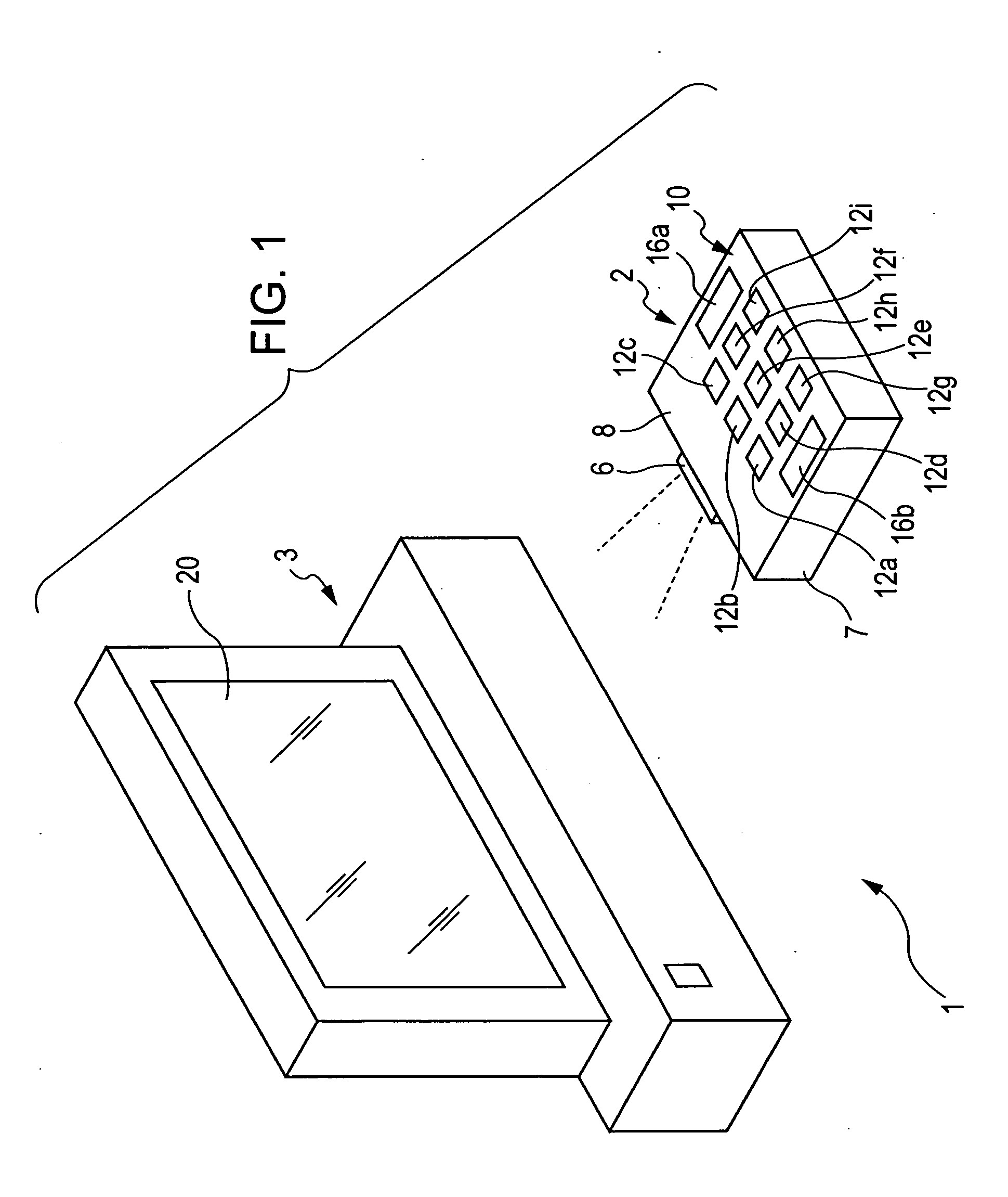
[0039] As shown in FIG. 3, the position-inputting region 8a includes nine buttons 12a, 12b, 12c, 12d, 12e, 12f, 12g, 12h, and 12i for confirming a selection in an XY array pattern. The buttons 12a to 12i are arranged so that the levels of these buttons are substantially the same as that of the operation surface 8, as viewed from the side. Each of the buttons 12a to 12i also displays a selection position for confirming a selection. In FIGS. 3 and 5, identifications are assigned to these buttons, i.e., “1”, “2”, . . . “9”. Alternatively, identifications other than numeric characters may be assigned to the buttons, or no identification may be assigned to the buttons.

[0040] As shown in FIG. 4, a protrusion 13 is formed at the center of the back surface of each of the buttons 12a to 12i to extend to the interior of the casing 7. The protrusions 13 extend through holes 4a formed in the coordinate detection unit 4 so as to extend past the back surface of the coordinate detection unit 4.

[...

second embodiment

[0079]FIG. 7 is a schematic view illustrating a typical screen of a display unit 20 according to the present invention.

[0080] In the second embodiment, the number of indices displayed on the display unit 20 is larger than the number of buttons 12a to 12i. Specifically, indices Ia, Ib, Ic, Id, Ie, If, Ig, Ih, and Ii are displayed in an array pattern corresponding to the array pattern of the buttons 12a to 12i. The index Ia overlaps an index Ia1, and the index Ia1 overlaps an index Ia2. The same arrangement is applicable to the indices Ib to Ii.

[0081] When a finger 35 in contact with the position-inputting region 8a moves, one of the indices Ia to Ii is highlighted in response to the position of the finger 35. FIG. 7 illustrates a state in which the finger 35 is in contact with the button 12d and the index Id is highlighted. In this state, when the button 12d is pushed and a corresponding switching element 15 is turned on, main data corresponding to the index Id is read out. At this ...


PUM


Abstract

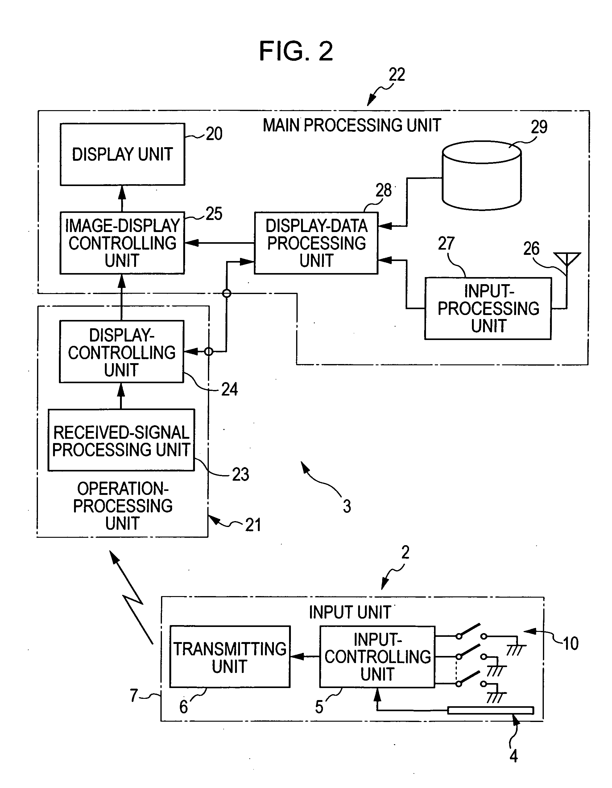
An image-processing apparatus includes an input unit for inputting operational signals. The input unit includes an operation surface and outputs, as the operational signals, a position detection signal representing a detected operation position of an operation instrument moving on the operation surface and a selection confirmation signal generated when a selection operation is confirmed on the operation position. The image-processing apparatus further includes a display unit and a display-controlling unit for controlling the display state of the display unit based on the operational signals. The display-controlling unit highlights an index corresponding to the operation position when the position detection signal is output in a state in which indices to be selected are displayed on the display unit, and reads and displays main data corresponding to the highlighted index when the selection confirmation signal is output.

Description

BACKGROUND OF THE INVENTION [0001] 1. Field of the Invention [0002] The present invention relates to image-processing apparatuses including display units for displaying various types of information, and more particularly to an image-processing apparatus for easily searching for various types of information to display the information. [0003] 2. Description of the Related Art [0004] Currently, display units for displaying image information have multiple functions, and, for example, digital television receivers can handle several tens of to several hundred channels that are selected by viewers. Other than digital television receivers, various types of terminal units installed in, for example, banks or retail stores also handle many information channels that are selected by users. Mobile data terminals also handle many information channels. [0005] An input device for operating the television receiver and various types of terminal units may be a remote controller that is connected to the...

Claims


Application Information

Patent Timeline
Patent Type & Authority Applications(United States)
IPC IPC(8): G06T17/00G08C17/02A63H29/22G08C23/04G09G5/00H01H9/16H01H13/702H01H25/00H01H25/04H02K11/00H02K23/00
CPCG08C17/02G08C23/04H01H13/702H01H2225/002H01H2225/03H04N21/42218H04N21/482H04N2005/4416H04N2005/443H04N2005/4441H01H2239/006H04N21/42212H04N21/42228H04N21/42224
Inventor SATO, TADAMITSU
Owner ALPS ALPINE CO LTD
Why Eureka
Try Eureka