Liquid crystal display device

Active Publication Date: 2005-11-24
AU OPTRONICS CORP
View PDF10 Cites 18 Cited by
  • Summary
  • Abstract
  • Description
  • Claims
  • Application Information

AI Technical Summary

Benefits of technology

[0064] According to the present invention, in a vertical alignment mode liquid crystal display device wherein liquid crystal molecules are aligned to be along the first direction due to the first alignment control pattern and the second alignment control pattern formed on the first substrate and the second substrate, respectively, because the spacer arrange

Problems solved by technology

This TN mode liquid crystal display device, however, is limited in a contrast ratio.
This limitation can be attributed to the operation principle of the TN mode liquid crystal display device.
In addition, it is difficult for the TN mode liquid crystal display device to provide a wide viewing angle, which is required by, for example, a desktop display.
In practice, however, pitches of the structures 25A and 25B are defined according to the response speed and transmission of the liquid crystal display device, and it is difficult to realize the ideal arrangeme

Method used


Image

  • Liquid crystal display device
  • Liquid crystal display device
  • Liquid crystal display device

Examples


first embodiment

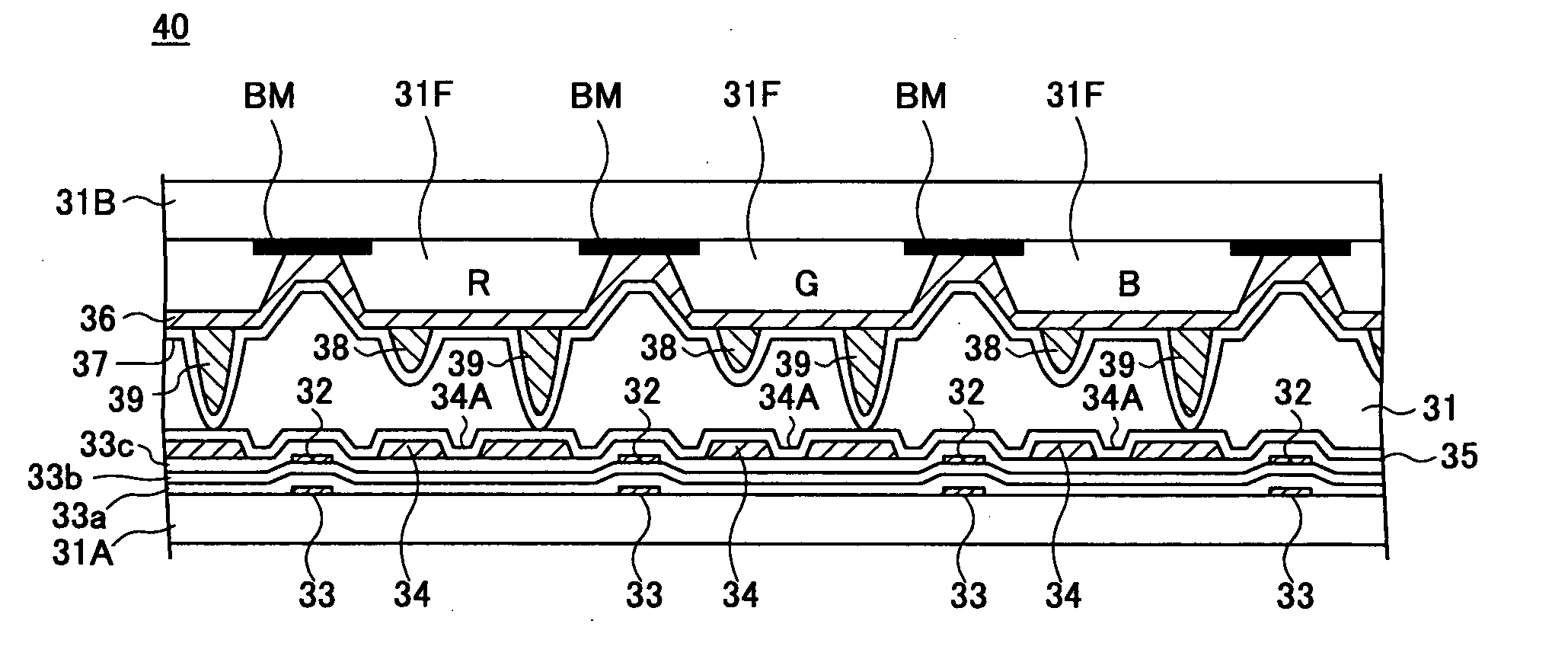
[0088]FIG. 9 is a schematic perspective view illustrating an example of a configuration of a liquid crystal display device 40 according to a first embodiment of the present invention.

[0089]FIG. 10A is an enlarged view of a portion of the liquid crystal display device 40 in FIG. 9.

[0090]FIG. 10B is an enlarged cross-sectional view of a portion of the liquid crystal display device 40 in FIG. 9.

[0091] As illustrated in FIG. 9, the liquid crystal display device 40 is an active-matrix liquid crystal display device, including a TFT glass substrate 31A and a TFT glass substrate 31B facing the TFT glass substrate 31A. The TFT glass substrate 31A carries plural thin film transistors (TFT) and a transparent pixel electrode cooperative with the TFTs, which corresponds to the electrode layer 23A as illustrated in FIG. 3 and FIG. 4. The TFT glass substrate 31B carries an electrode formed on the TFT glass substrate 31A, which corresponds to the electrode layer 23B. A liquid crystal layer 31 in...

second embodiment

[0107]FIG. 12 is a plan view illustrating a configuration of a liquid crystal display device 50 according to a second embodiment of the present invention. In FIG. 12, the same reference numbers are used for the same elements as those described previously, and overlapping descriptions are omitted.

[0108] As illustrated in FIG. 12, the projecting pattern 38 and the cutouts 34A are formed to extend on the pixel electrode 34 in a zigzag manner and in parallel to each other. In the second embodiment, the cutout pattern 34A is formed only at the center portion of the pixel electrode 34, but not arranged outside the center portion, specifically, not arranged outside the projecting pattern 38. Due to this arrangement, the constraint on the alignment of the liquid crystal molecules 22A applied by the projecting pattern 38 is in effect even up to the outer edge of the pixel electrode 34.

[0109] In the second embodiment, similarly, the columnar spacers 39 are also formed on the scanning electr...

third embodiment

[0113]FIG. 13 is a plan view illustrating a configuration of a liquid crystal display device 60 according to a third embodiment of the present invention. In FIG. 13, the same reference numbers are used for the same elements as those described previously, and overlapping descriptions are omitted.

[0114] As illustrated in FIG. 13, in the present embodiment, in addition to the structure shown in FIG. 11 or FIG. 12, the columnar spacer 39 is arranged such that the cutout patterns 34A are formed between two projecting patterns 38 opposite to each other on the electrode pattern 31C, which produces the auxiliary capacitance Cs, and the edges of the columnar spacer 39 are in parallel to the cutout patterns 34A.

[0115] In the structure in FIG. 13, between the columnar spacer 39 and the projecting pattern 38, the columnar spacer 39, the projecting pattern 38, and the cutout patterns 34A cooperate with each other so as to regulate the alignment direction of the liquid crystal molecules to be s...


PUM


Abstract

A liquid crystal display device is disclosed that is capable of suppressing disorder of alignment of liquid crystal molecules caused by a spacer arranged between two TFT substrates. In liquid crystal display device, the spacer arranged between the two TFT substrates is capable of aligning liquid crystal molecules near the spacer along a specified direction.

Description

CROSS-REFERENCE TO RELATED APPLICATION [0001] This patent application is based on Japanese Priority Patent Application No. 2004-153923 filed on May 24, 2004, the entire contents of which are hereby incorporated by reference. BACKGROUND OF THE INVENTION [0002] 1. Field of the Invention [0003] The present invention generally relates to a liquid crystal display device, and particularly, to a liquid crystal display device operating in a vertical (homeotropic) alignment mode. [0004] 2. Description of the Related Art [0005] Because a liquid crystal display device has low power consumption and can be made compact, it is widely used in various portable information processing devices, such as a laptop computer, or a cellular phone. On the other hand, so far, performance of the liquid crystal display device has been improved significantly, and the latest liquid crystal display devices have such high response speed and contrast ratio that they can be used in a desktop computer or a workstation...

Claims


Application Information

Patent Timeline
IPC IPC(8): G02F1/1339G02F1/1333G02F1/1337G02F1/1343G02F1/139
CPCG02F1/1393G02F1/133707G02F1/1337G02F1/1343
Inventor TAKEDA, ARIHIROSASAKI, TAKAHIROSAWASAKI, MANABU
Owner AU OPTRONICS CORP
Why Eureka
Try Eureka