Parallel processing device and parallel processing method
a processing device and parallel processing technology, applied in the field of parallel processing apparatus, can solve the problems of prolonging the time required, reducing the effect of parallel processing speed, and reducing the time required to totalize true cells
- Summary
- Abstract
- Description
- Claims
- Application Information
AI Technical Summary
Problems solved by technology
Method used
Image

Examples
first embodiment
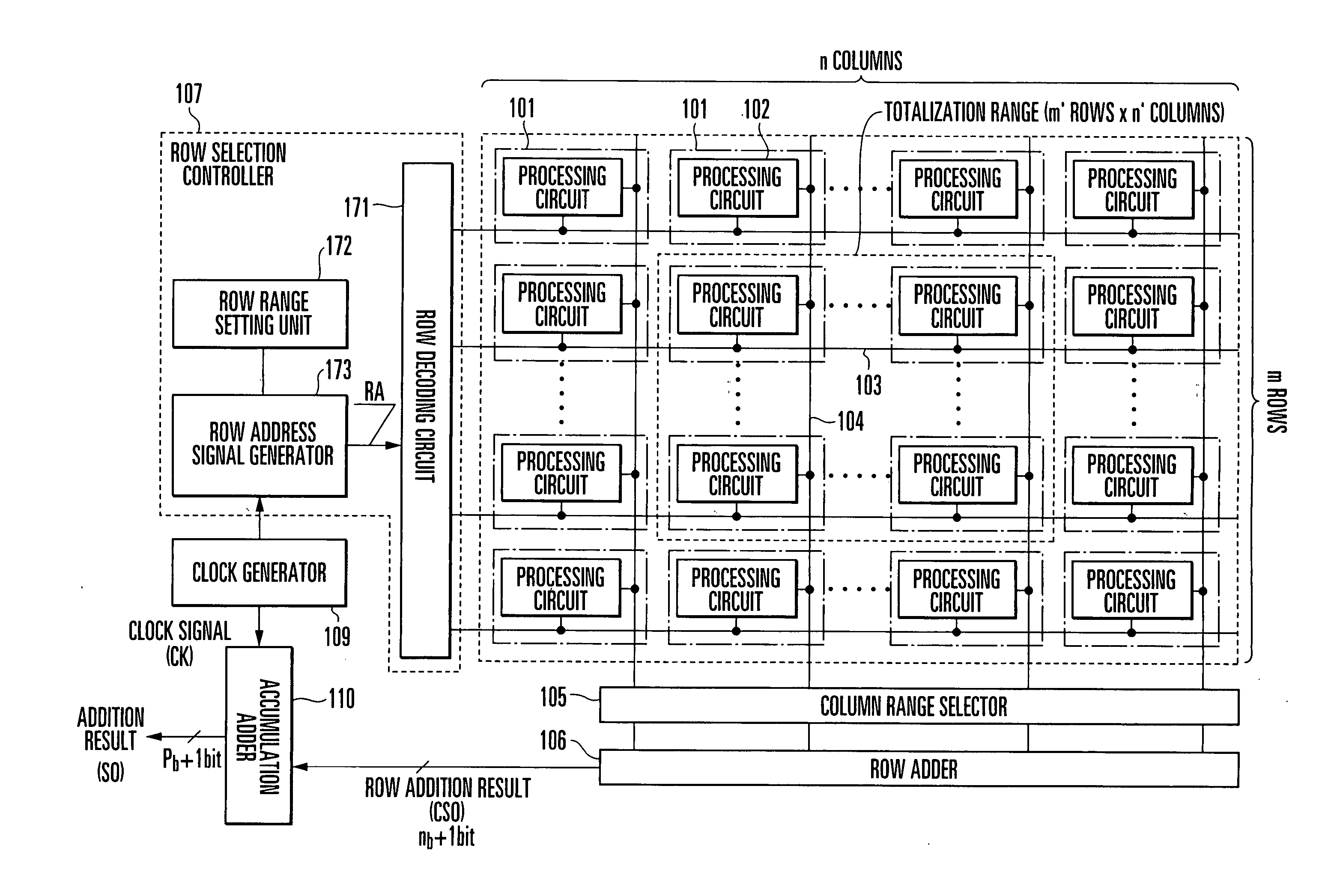
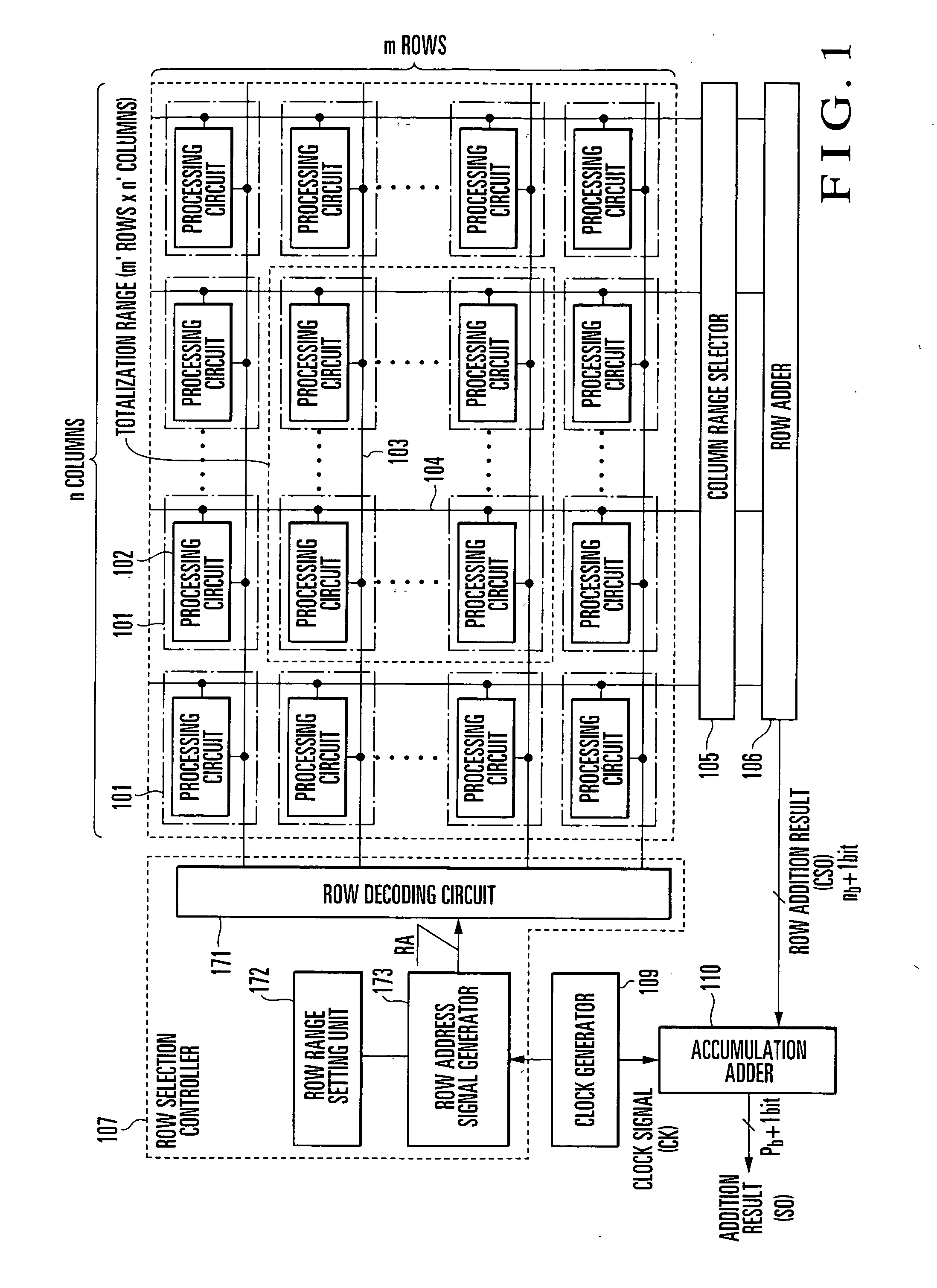
[0052]FIG. 1 is a view showing an example of the arrangement of a parallel processing apparatus according to the first embodiment of the present invention. This parallel processing apparatus is made up of cells 101 arranged into m rows×n columns, a column range selector 105, a row adder 106, a row selection controller 107, and an accumulation adder 110. Each cell 101 has a processing circuit 102 for performing predetermined processing. The row selection controller 107 has a row decoding circuit 171 connecting to select signal lines 103, a row range setting unit 172, and a row address signal generator 173. The input and output of each processing circuit 102 are connected to the select signal line 103 and a data bus (data output line) 104, respectively.
[0053] The select signal line 103 corresponding to each row is connected to the row decoding circuit 171 of the row selection controller 107. The data bus 104 corresponding to each column is connected to the row adder 106 via the colum...
second embodiment
[0072] The column range selector 105 will be explained in more detail below. FIG. 4 is a view showing an example of the arrangement of the column range selector 105 in the parallel processing circuit shown in FIG. 1. The column range selector 105 shown in FIG. 4 is characterized by comprising an output enable signal generator 151, a column range setting unit 152, and output enabling circuits 153 formed in one-to-one correspondence with the data buses 104.
[0073] The output enabling circuit 153 controls an output signal from the data bus 104, in accordance with an output enable signal from the output enable signal generator 151. If the output enable signal is “enable”, the signal from the data bus 104 is directly output. If the output enable signal is “disable”, “0” (zero) is output. In this way, only processing results from the processing circuits 102 of the cells 101 within the designated totalization range (column range) can be added without changing the arrangement of the row add...
third embodiment
[0077] The output enable signal generator will be described in more detail below. FIG. 6 is a view showing an example of the arrangement of the output enable signal generator 151 in the column range selector 105 shown in FIG. 4. The output enable signal generator 151 shown in FIG. 6 is characterized by comprising a column decoding circuit 501, a column address signal generator 502, an initializing circuit 503, and a plurality of storage circuits 504 corresponding to the output enabling circuits 153.
[0078] Each storage circuit 504 holds an output enable signal to be output to the output enabling circuit 153. This output enable signal can be set in the storage circuit 504 as follows. First, the storage circuits 504 are initialized by the initializing circuit 503. After that, by selecting columns to be enabled to output data, an output enable signal is set in the corresponding storage circuits 504. Rows to be enabled to output data are set in the column range setting unit 152, and the...
PUM
 Abstract
Description
Claims
Application Information
 - R&D Engineer
- R&D Manager
- IP Professional
- Industry Leading Data Capabilities
- Powerful AI technology
- Patent DNA Extraction
Browse by: Latest US Patents, China's latest patents, Technical Efficacy Thesaurus, Application Domain, Technology Topic.
© 2024 PatSnap. All rights reserved.Legal|Privacy policy|Modern Slavery Act Transparency Statement|Sitemap