Method for determining frequency of power brush in vacuum cleaner

a technology of power brush and vacuum cleaner, which is applied in the direction of vacuum cleaners, cleaning processes and apparatuses, applications, etc., can solve the problems of high power consumption, achieve the effect of maximizing cleaning efficiency, minimizing noise and vibration, and large amount of movemen

Inactive Publication Date: 2005-12-01
LG ELECTRONICS INC
View PDF6 Cites 8 Cited by
  • Summary
  • Abstract
  • Description
  • Claims
  • Application Information

AI Technical Summary

Benefits of technology

[0020] With a method for determining a frequency of a power brush in a vacuum cleaner according to the present invention, a large amount of movement can be obtained with a small amount of power through the use of resonance where the mechanical oscillation frequency of the driving unit corresponds to the driving frequency of the power supply unit.
[0021] Furthermore, the mechanical oscillation frequency of the driving unit can be set a prescribed percentage higher or lower than the driving frequency of the power supply unit according to the present invention, whereby noise and vibration is minimized while cleaning efficiency is maximized.

Problems solved by technology

In the conventional method for raising the waste from the floor through the use of the brush 5 as described above, however, the power used to raise the waste from the floor is fully supplied from the motor 6 with the result that power consumption is high.

Method used


Image

  • Method for determining frequency of power brush in vacuum cleaner
  • Method for determining frequency of power brush in vacuum cleaner
  • Method for determining frequency of power brush in vacuum cleaner

Examples


Embodiment Construction

[0027] Now, a preferred embodiment of the present invention will be described in detail with reference to the accompanying drawings.

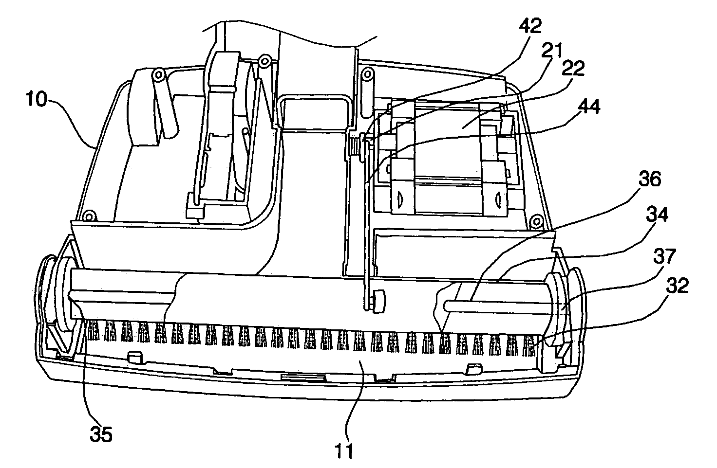
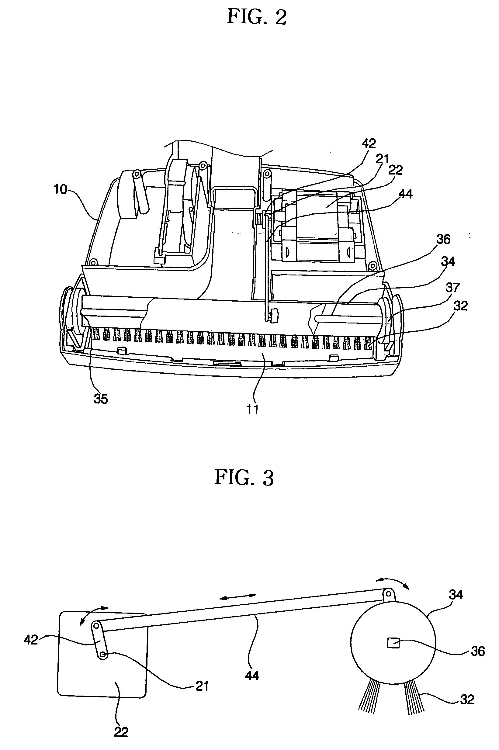
[0028]FIG. 2 is a perspective view showing the interior of a suction head of a vacuum cleaner according to a preferred embodiment of the present invention, FIG. 3 is a side view schematically showing a power transmission part of the suction head shown in FIG. 2, and FIG. 4 is a graph illustrating experimental values of operating angles based on a driving frequency of a power brush of the present invention.

[0029] As shown in FIG. 2, the suction head of the vacuum cleaner according to the present invention comprises a head body 10 having a suction hole 11 formed therein, and a power brush attached to the head body 10.

[0030] The power brush comprises a power supply unit, and a driving unit driven by means of the power supply unit for raising waste from the floor.

[0031] Preferably, the power supply unit comprises a motor 22, which is driven by means of ...


PUM


Abstract

Disclosed herein is a method for determining a frequency of a power brush in a vacuum cleaner. According to the method of the present invention, a mechanical oscillation frequency of a driving unit, which includes a brush body reciprocated within a range of prescribed angles, and a torsion bar for providing a prescribed elastic force to angular rotation of the brush body, is set equally to a driving frequency of a power supply unit, which drives the driving unit, or is set a prescribed percentage higher or lower than the driving frequency of the power supply unit, so that the driving unit can resonate. A large amount of movement is obtained using a small amount of power by means of the resonance.

Description

BACKGROUND OF THE INVENTION [0001] 1. Field of the Invention [0002] The present invention relates to a power brush of a vacuum cleaner, and more particularly to a method for determining a frequency of a motor that drives a power brush of a vacuum cleaner. [0003] 2. Description of the Related Art [0004]FIG. 1 is an exploded perspective view, in part, showing a suction head of a conventional vacuum cleaner. [0005] As shown in FIG. 1, the suction head of the conventional vacuum cleaner comprises a head body 1 having a suction hole 2 for sucking waste off of the floor, and a brush unit 3 for raising waste from the floor to suck in the waste more efficiently through the suction hole 2. [0006] The brush unit 3 comprises a brush body 4 rotatably mounted in the head body 1, a brush 5 attached to the surface of the brush body 4 such that ends of a plurality of brush parts constituting the brush 5 are implanted into the brush body 4, a power transmission part for rotating the brush body 4, an...

Claims


Application Information

Patent Timeline
Patent Type & Authority Applications(United States)
IPC IPC(8): A47L9/04A47L9/28A47L11/24
CPCA47L9/0411A47L9/04
Inventor YOO, MYUNG KEUNLIM, JUN YOUNGLEE, YO HANKIM, SANG YOUNG
Owner LG ELECTRONICS INC
Why Eureka
Try Eureka