Stand device for portable electronic device

a technology for electronic devices and stands, which is applied in the direction of instruments, furniture parts, and electrical apparatus casings/cabinets/drawers, etc., can solve the problems of difficult smooth removal and inability to easily separate the electronic devices from the stand devices, and achieve the effect of longer movement distan

Active Publication Date: 2012-01-05
SONY COMPUTER ENTERTAINMENT INC
View PDF3 Cites 44 Cited by
  • Summary
  • Abstract
  • Description
  • Claims
  • Application Information

AI Technical Summary

Benefits of technology

[0012]Further, according to this aspect, the guide portion may be provided to the pedestal. With this arrangement, a constant moving direction of the slider relative to the pedestal can be ensured.
[0013]Further, according to this aspect, the pedestal may be provided with a connector projecting from the support surface, and the guide portion may guide the slider to move in a direction in which the connector projects. With this arrangement, in removing the electronic device from the stand device, the connector of the electronic device can be smoothly separated from the connector of the stand device.
[0014]Further, according to this aspect, the support portion may be formed extending in a radial direction of the fulcrum portion, and the slider may include a contact portion for contacting on the support portion. Further, the guide portion may support the slider such that the contact portion moves on the support portion toward a distal end of the support portion while the support portion moves upward around the fulcrum portion. A movement amount of the slider relative to the turn degree of the lever is larger when the support portion presses up the sliding remember at a position closer to the distal end, compared to a case in which the support portion presses up the slider at a position closer to the fulcrum portion. Therefore, according to a structure in which the contact portion moves on the support portion toward the distal end, a longer movement distance can be ensured for the slider, compared to a structure in which the support portion presses up the slider only at a position closer to the fulcrum portion.

Problems solved by technology

For example, when the connector of a stand device remains rigidly inserted into the connector of an electronic device, the electronic device is not readily separated from the stand device.
In such a case, for example, a user needs to lift the electronic device on one hand while holding the stand device on the other hand, which makes smooth removal difficult.

Method used


Image

  • Stand device for portable electronic device
  • Stand device for portable electronic device
  • Stand device for portable electronic device

Examples


Embodiment Construction

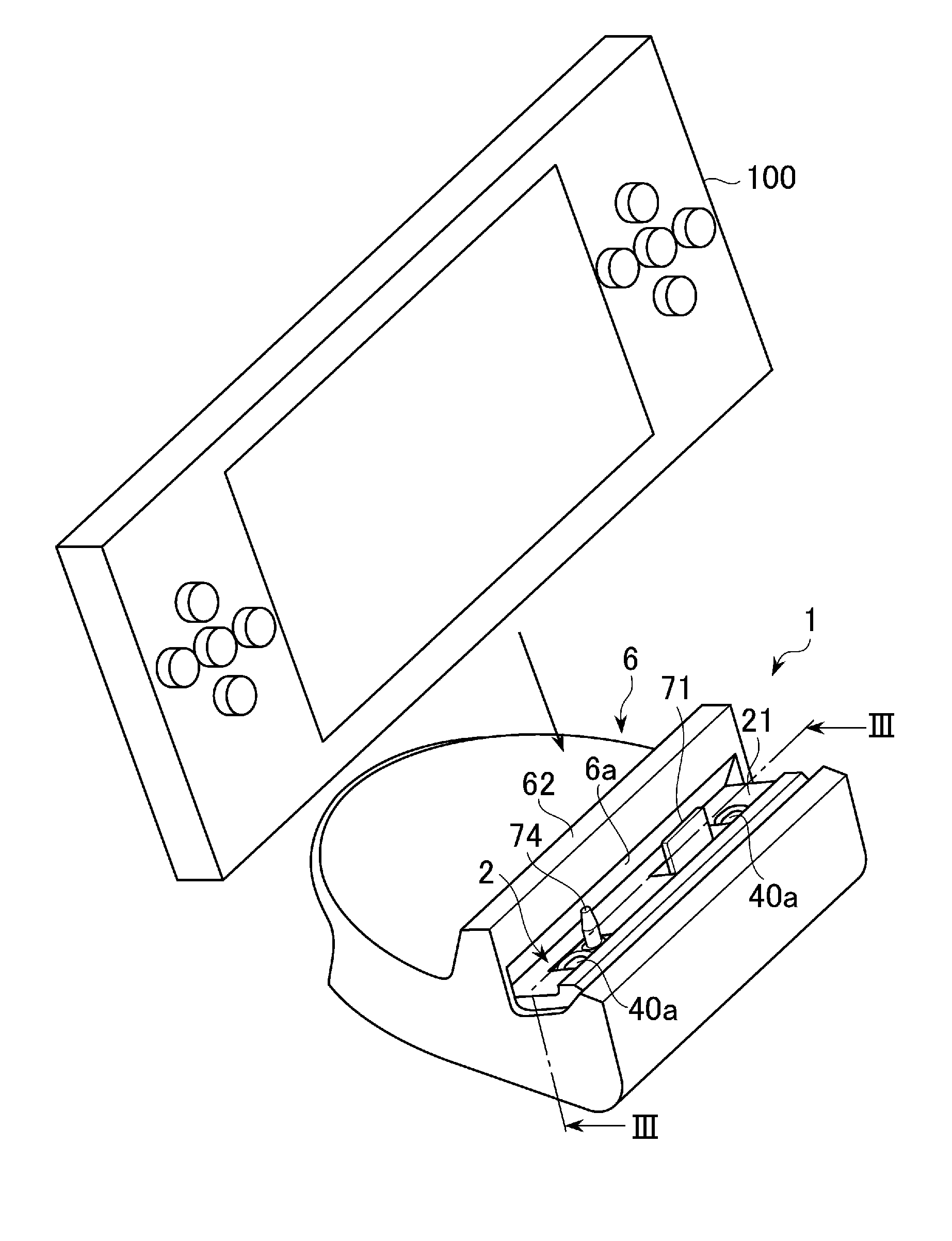
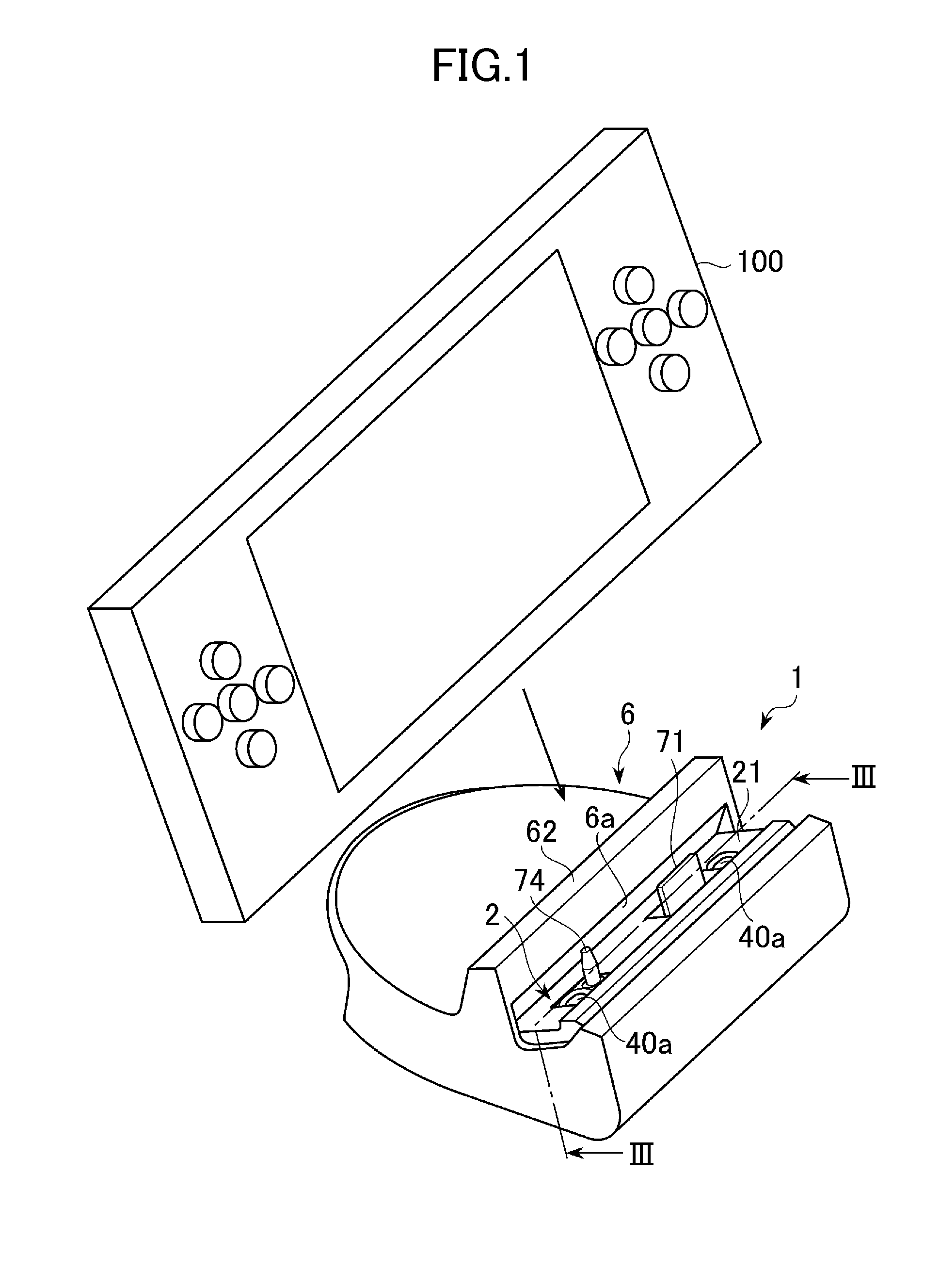
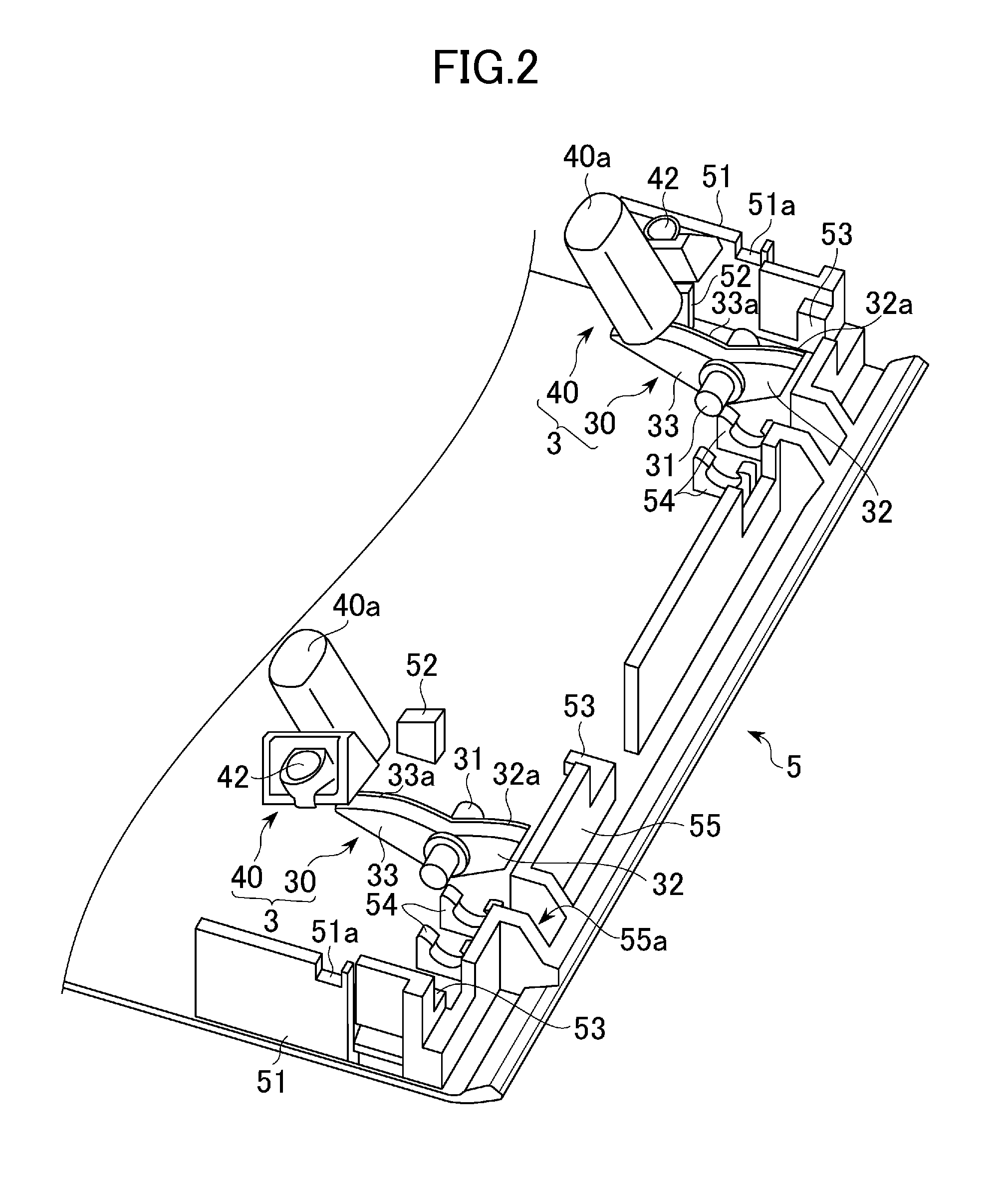
[0031]In the following, one embodiment of the present invention will be described with reference to the accompanying drawings. FIG. 1 is a perspective view of a stand device 1, which is an example of an embodiment of the present invention. FIG. 2 is an exploded perspective view of a lever mechanism 3 and a base plate 5 provided in the stand device 1. FIG. 3 is a cross sectional view along the line III-III shown in FIG. 1 obtained by cutting the stand device 1 along a cross section perpendicular to the support surface portion 21 of the pedestal 2. FIG. 4 is a cross sectional view along the line IV-IV shown in FIG. 3. FIG. 5 is across sectional view obtained by cutting the stand device 1 along the cross section same as that in the cross sectional view of FIG. 4, showing the pedestal 2 of the stand device 1 having turned from the position shown in FIG. 4. FIG. 6 is an enlarged diagram of FIG. 3, showing the lever mechanism 3. FIG. 7 is a cross sectional view of the stand device 1, show...


PUM


Abstract

To provide a stand device capable of improving workability in removing a portable electronic device. A stand device has a pedestal and a lever mechanism. The pedestal is supported movable between a support portion for supporting an electronic device mounted on the support surface and a removal position at which the pedestal is arranged through a movement thereof in which the pressing portion descends. The lever mechanism includes a pressed arm and a projection. The pressed arm is pressed by the pressing portion to thus move downward when the pedestal moves from the support position to the removal position. The projection moves upward along with the rotation of the fulcrum portion caused by the downward movement of the pressed arm to thus project from the support surface of the pedestal.

Description

TECHNICAL FIELD[0001]The present invention relates to a stand device for supporting and charging, and so forth, a portable electronic device, such as a portable phone, a portable game device, a camera, and so forth, and in particular to a technique for improving workability in removing an electronic device from a stand device.BACKGROUND ART [0002]Conventionally, stand devices for standing a portable electronic device, such as a portable phone, a portable game device, and so forth, and electrically connecting to the electronic device have been used (e.g., Patent Document 1). Such a stand device has, on the top surface thereof, a connector for connecting to a connector of an electronic device. Electric charge for the electronic device and data exchange between the electronic device and a peripheral device connected to the stand device are performed through the connector.Prior Art DocumentPatent DocumentPatent Document 1: Japanese Patent Laid-open Publication No. 2007-96883DISCLOSURE O...

Claims


Application Information

Patent Timeline
Patent Type & Authority Applications(United States)
IPC IPC(8): H05K7/00
CPCH04M1/04H02J7/0044
Inventor TAKAHASHI, NOBUYUKIISHIWATA, NOBUYOSHI
Owner SONY COMPUTER ENTERTAINMENT INC
Why Eureka
Try Eureka