Method for energy-saving elevator control and elevator installation

a technology for elevators and installation methods, applied in elevators, sustainable buildings, mine lifts, etc., to achieve the effect of shortening the round trip time and suitable travel load

Inactive Publication Date: 2005-12-01
INVENTIO AG
View PDF9 Cites 21 Cited by
  • Summary
  • Abstract
  • Description
  • Claims
  • Application Information

AI Technical Summary

Benefits of technology

[0027] It is advantageous if during the activated energy-saving mode in the case of allocation of new destination calls the otherwise usual limitation of the number of intermediate stops, which is usual with the cost-optimizing allocation, is cancelled. This number of intermediate stops is indirectly influenced by the monitoring of the tolerable waiting time and the tolerable travel time to the destination. Limitation of the number of intermediate stops normally serves for shortening the round trip times in the cost-optimizing allocation of destination calls.
[0028] In an advantageous refinement of the present invention when the energy-saving mode is activated and with new input of a destination call this destination call is allocated to the elevator which has the longest common travel path with suitable elevator load. The suitable elevator load was described above. In order to be able to make a statement with respect thereto the common travel paths by the destination call to be allocated and the instantaneously checked elevator have to be compared. This advantageous allocation of the elevator which has the longest common travel path with suitable travel load reduces, inter alia, the number of intermediate stops.

Problems solved by technology

This is partly due to the fact that the demands on elevator installations on the one hand to make available a maximum transport performance and on the other hand to operate in an energy-saving manner are in part mutually contradictory.

Method used


Image

  • Method for energy-saving elevator control and elevator installation
  • Method for energy-saving elevator control and elevator installation
  • Method for energy-saving elevator control and elevator installation

Examples


Embodiment Construction

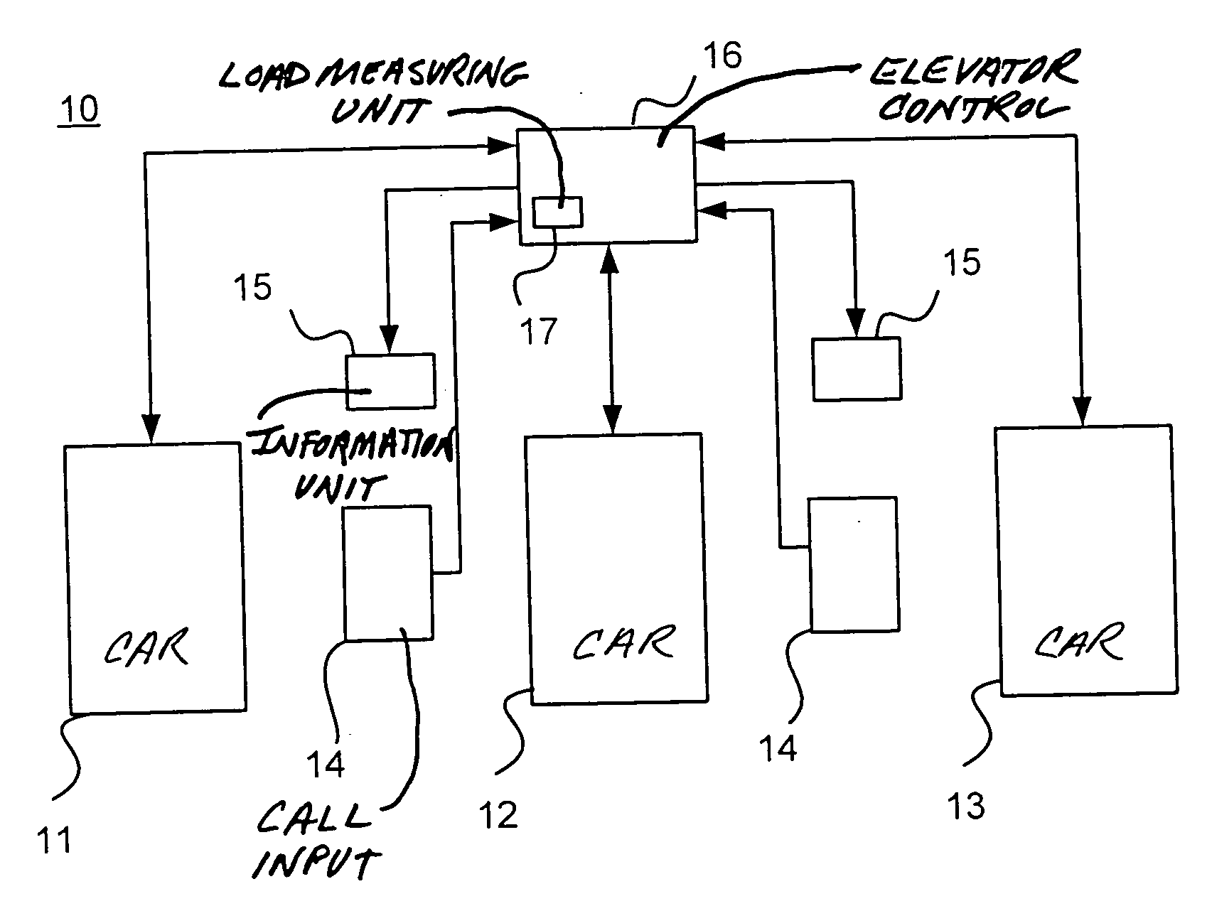
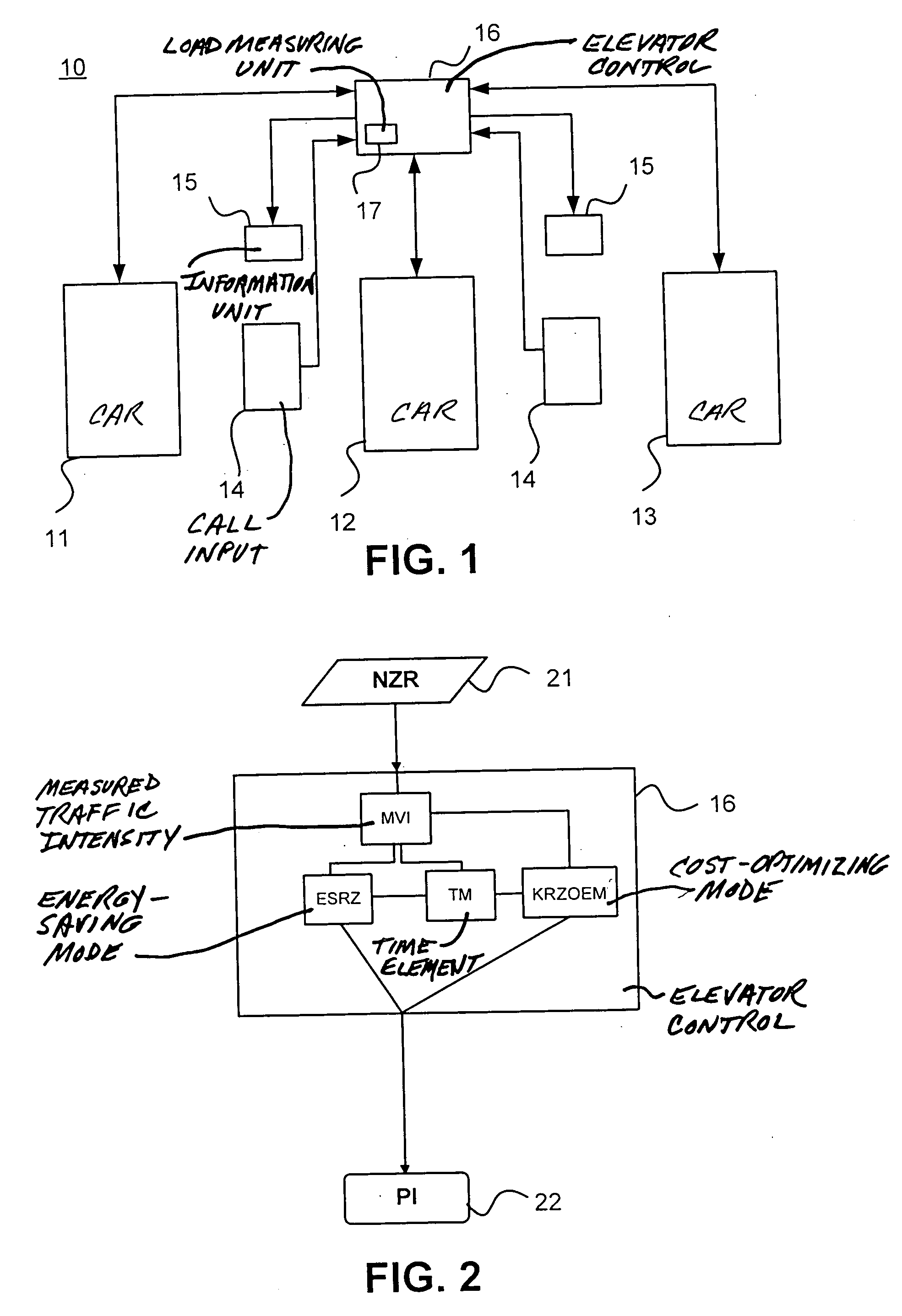
[0040] An elevator installation 10 according to the present invention is shown in FIG. 1. The elevator installation 10 according to the present invention comprises three elevators 11, 12 and 13. The three elevators 11, 12 and 13 are controlled by an elevator control 16. For simplification of the illustration, depiction of drive units and elevator shafts has been dispensed with. A respective destination call is input by the passengers by way of destination call input apparatus 14 and transmitted to the elevator control 16. The elevator control 16 ascertains the elevator 11, 12, 13 most favorable for this destination call and communicates to the passenger the ascertained elevator 11, 12 or 13 by way of the information unit 15. Moreover, a load measuring unit 17 by means of which a load measurement of the individual elevators can be undertaken is arranged in the elevator control 16, wherein the load-receiving parts of the load-measuring unit 17 are arranged at the elevators 11, 12, 13 ...


PUM


Abstract

A method of controlling an elevator installation with several elevators, in which destination call inputs of passengers are input by destination call input apparatus and in which at least one traffic criterion, which characterizes a traffic intensity, of the elevator installation is measured by an elevator control, wherein the elevator control allocates cost-optimizing elevators to the destination call inputs. In order to obtain an energy saving without prejudicing the transport capacity of the elevator installation, the elevator control additionally allocates energy-optimizing elevators to the destination call inputs in dependence on the traffic criterion.

Description

BACKGROUND OF THE INVENTION [0001] The present invention relates to a method of controlling an elevator installation with several elevators. The passengers input their travel wishes in the form of destination call inputs by way of a destination call input apparatus. An elevator control measures at least one traffic criterion, which characterizes a traffic intensity, of the elevator installation, wherein the elevator control allocates the elevators in an energy-optimizing manner to the destination call inputs of passengers. The present invention further relates to an elevator installation for carrying out the above-mentioned method. [0002] Modern elevator installations operate in a manner controlled by destination calls. A passenger inputs his or her travel destination by way of a destination call input apparatus so that an elevator control can select an elevator from several elevators for corresponding destination call inputs in a cost-optimizing manner and allocate it to this passe...

Claims


Application Information

Patent Timeline
Patent Type & Authority Applications(United States)
IPC IPC(8): B66B1/18B66B1/20B66B1/46
CPCB66B1/18B66B19/007Y02B50/122Y02B50/00
Inventor KOSTKA, MIROSLAV
Owner INVENTIO AG
Why Eureka
Try Eureka