Hub unit for use in electrically movable wheels and vehicle comprising the hub unit

Inactive Publication Date: 2005-12-01
SANYO ELECTRIC CO LTD
View PDF4 Cites 44 Cited by
  • Summary
  • Abstract
  • Description
  • Claims
  • Application Information

AI Technical Summary

Benefits of technology

[0012] In the case where the fixing support shaft has opposite ends projecting outward from the respective opposite ends of the hub 7, the hub unit is more simp

Problems solved by technology

Furthermore, the three shafts 41, 57, 57a are likely to be out of alignment owing to errors involved

Method used


Image

  • Hub unit for use in electrically movable wheels and vehicle comprising the hub unit
  • Hub unit for use in electrically movable wheels and vehicle comprising the hub unit
  • Hub unit for use in electrically movable wheels and vehicle comprising the hub unit

Examples


Embodiment Construction

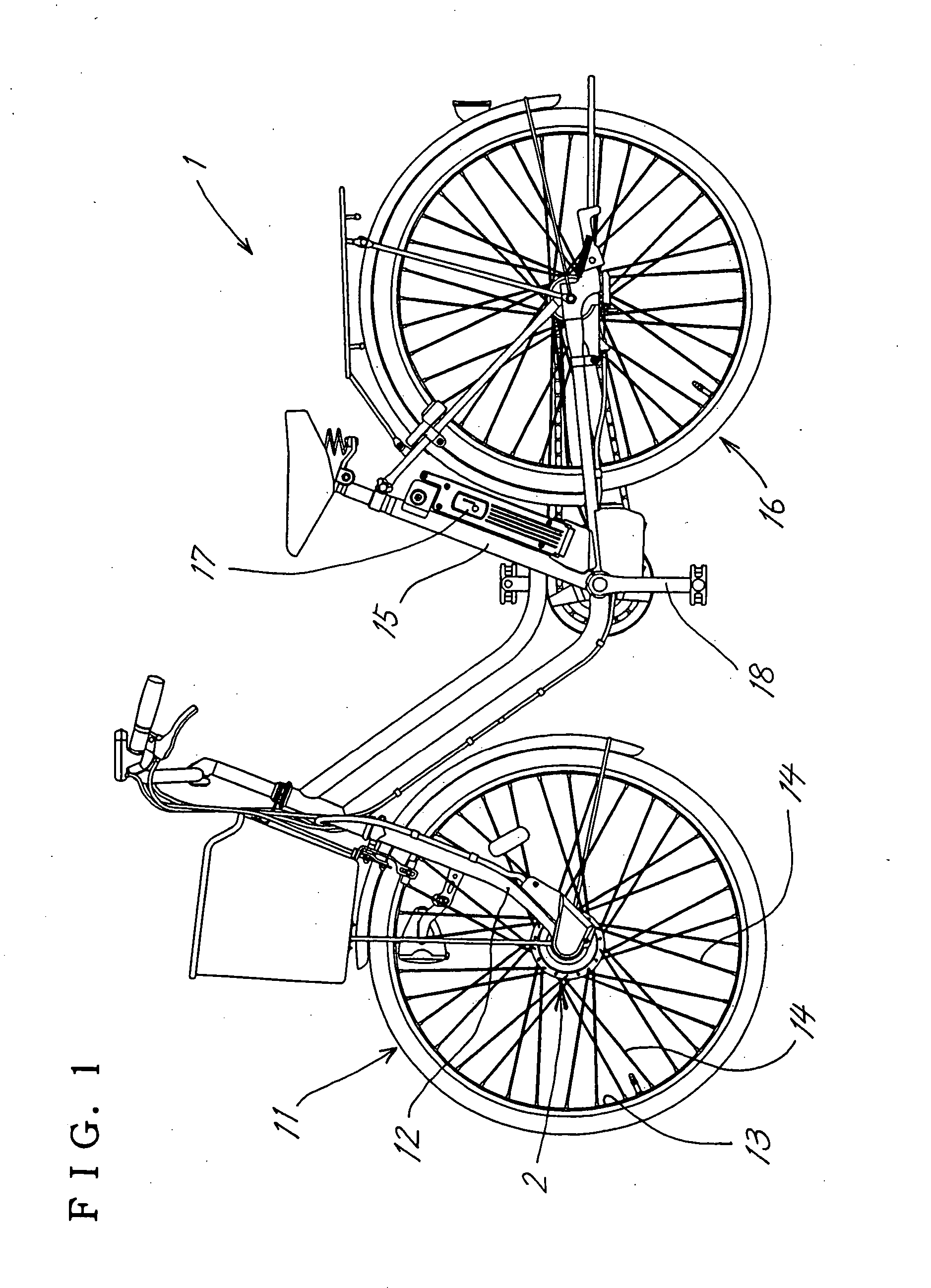
[0022]FIG. 1 shows an example of electrically assisted bicycle 1 having a hub unit 2 of the present invention.

[0023] A hub unit 2 is attached to the lower end of a front fork 12 of the bicycle 1, and the hub unit 2 and the rim 13 of a front wheel 11 are interconnected by spokes 14, 14.

[0024] A battery 17 is mounted on the bicycle between a seat post 15 and a rear wheel 16.

[0025] A sensor (not shown) is provided on a suitable portion on which the pedaling force of the pedals 18 acts for energizing a motor 9 of the hub unit 2 by the battery 17 when the load on the pedals is not smaller than a predetermined value.

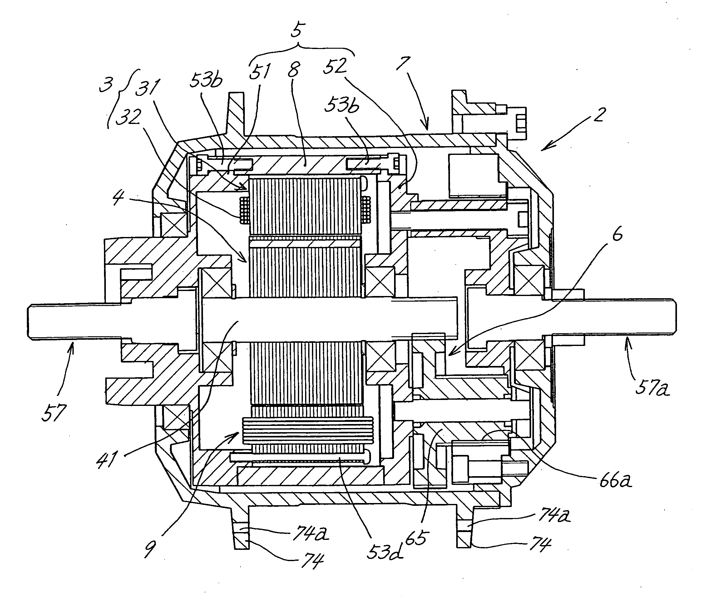
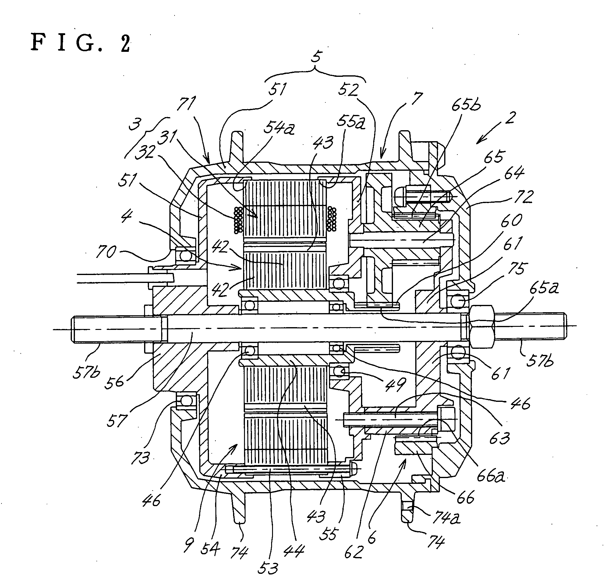
[0026] The hub unit 2 has the above-mentioned motor 9 which comprises a stator 3 and a rotor 4, a hub 7 enclosing the motor 9 therein and rotatingly driven by the rotation of the rotor 4, and a fixing support shaft 57 secured to a motor housing, 5, projecting therefrom in alignment with the axis of rotation of the hub 7 and having opposite ends extending outward from the h...


PUM


Abstract

A hub unit wherein the axis is prevented from deflecting for use in electrically assisted bicycles. A single fixing support shaft (57) has opposite ends projecting outward respectively from opposite ends of a hub (7) enclosing a motor (9) and a planetary gear reduction mechanism (6) therein and having inner teeth (66a) in mesh with planetary gears (65). The rotor (4) of the motor (9) has a tubular rotating shaft (44) rotatably fitted around the support shaft (57) and is therefore rotatable free of deflection of its axis relative to the support shaft (57). The hub unit is more simplified in construction and easier to assemble than the conventional hub unit wherein the rotating shaft of the rotor (4) is separate from the support shaft (57).

Description

FIELD OF THE INVENTION [0001] The present invention relates to hub units for use in electrically movable wheels, and to electrically assisted bicycles, wheelchairs and like vehicles comprising the hub unit. BACKGROUND OF THE INVENTION [0002]FIG. 8 shows an electrically movable wheel hub unit 2 for an electrically assisted bicycle. [0003] The electrically movable wheel hub unit (hereinafter referred to as the “hub unit”) has a motor 9 comprising a stator 3 and a rotor 4, a planetary gear reduction mechanism 6 coupled to a rotor shaft 41 extending through an end plate 52 of a motor housing 5, a hub 7 enclosing the motor 9 and the reduction mechanism 6 therein and having inner teeth 66a in mesh with planetary gears 65, and fixing support shafts 57, 57a in alignment with the rotor shaft 41 and projecting outward respectively from an end plate 51 on one side of the motor housing 5 opposite to the reduction mechanism 6 and from a planetary gear support frame 61, the support shafts 57, 57a...

Claims


Application Information

Patent Timeline
IPC IPC(8): B60B27/02B62M6/65B60B27/00B62M7/12H02K5/00H02K5/15H02K7/116
CPCB60B27/02Y02T10/641H02K5/00H02K5/15H02K7/116B60B27/0021B60B27/0005B60L11/007B60L11/1877B60L2200/12B60L2220/14B60L2220/44B60L2250/26B60L2220/50B60L3/0061B60L2240/36Y02T10/7005Y02T10/705B62M6/65B60L50/20B60L50/66Y02T10/64Y02T10/70
Inventor TANAKA, TATSUAKITOMOSHIGE, KAZUHIROADACHI, RYOHEI
Owner SANYO ELECTRIC CO LTD
Why Eureka
Try Eureka