Surface acoustic wave device
a surface acoustic wave and waveguide technology, applied in piezoelectric/electrostrictive/magnetostrictive devices, piezoelectric/electrostriction/magnetostriction machines, electrical equipment, etc., can solve the problems of reducing the characteristic demands affecting the performance of the saw device, so as to improve the power durability and reduce the resistance. , the effect of reducing th
- Summary
- Abstract
- Description
- Claims
- Application Information
AI Technical Summary
Benefits of technology
Problems solved by technology
Method used
Image
Examples
first embodiment
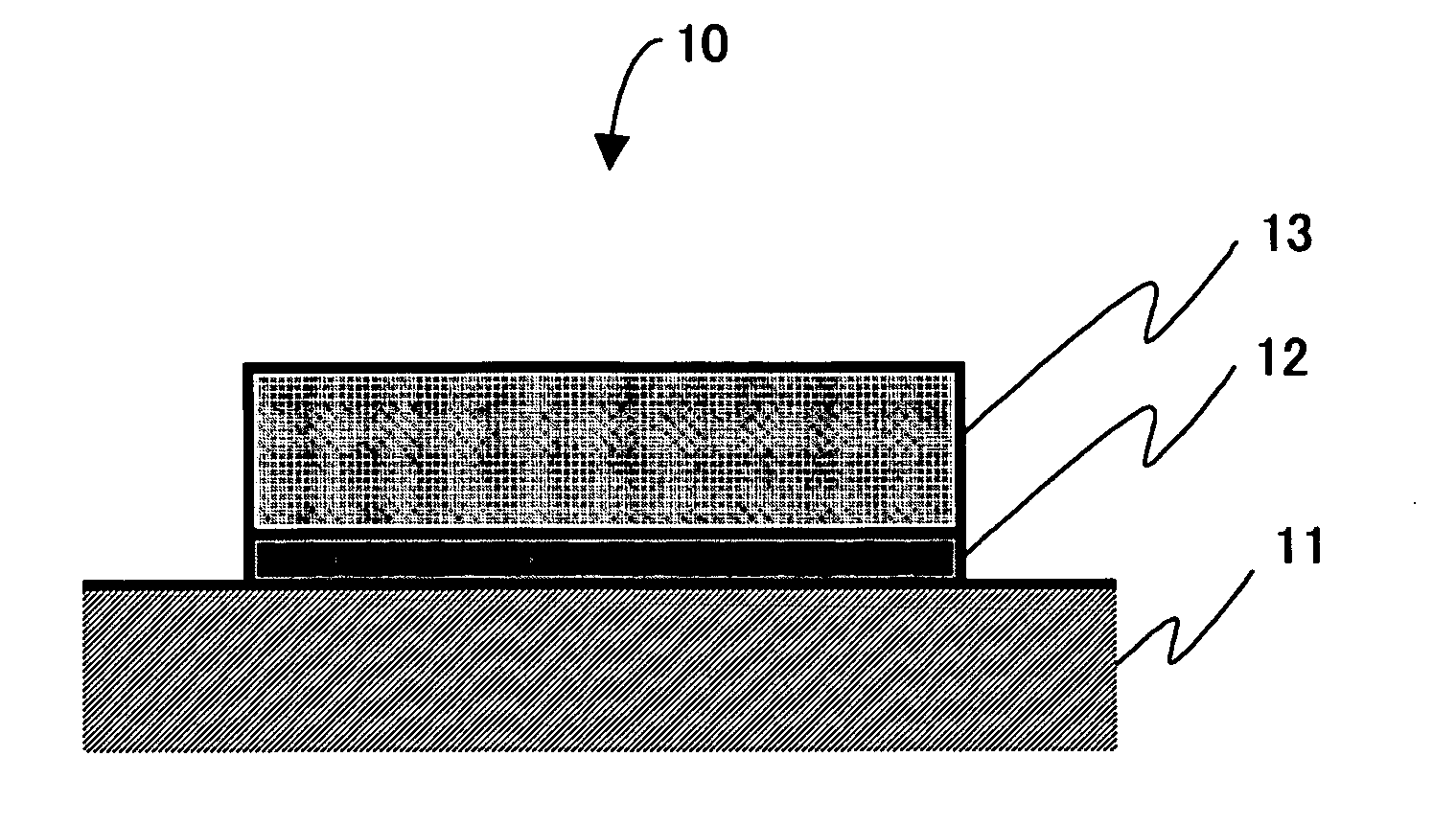
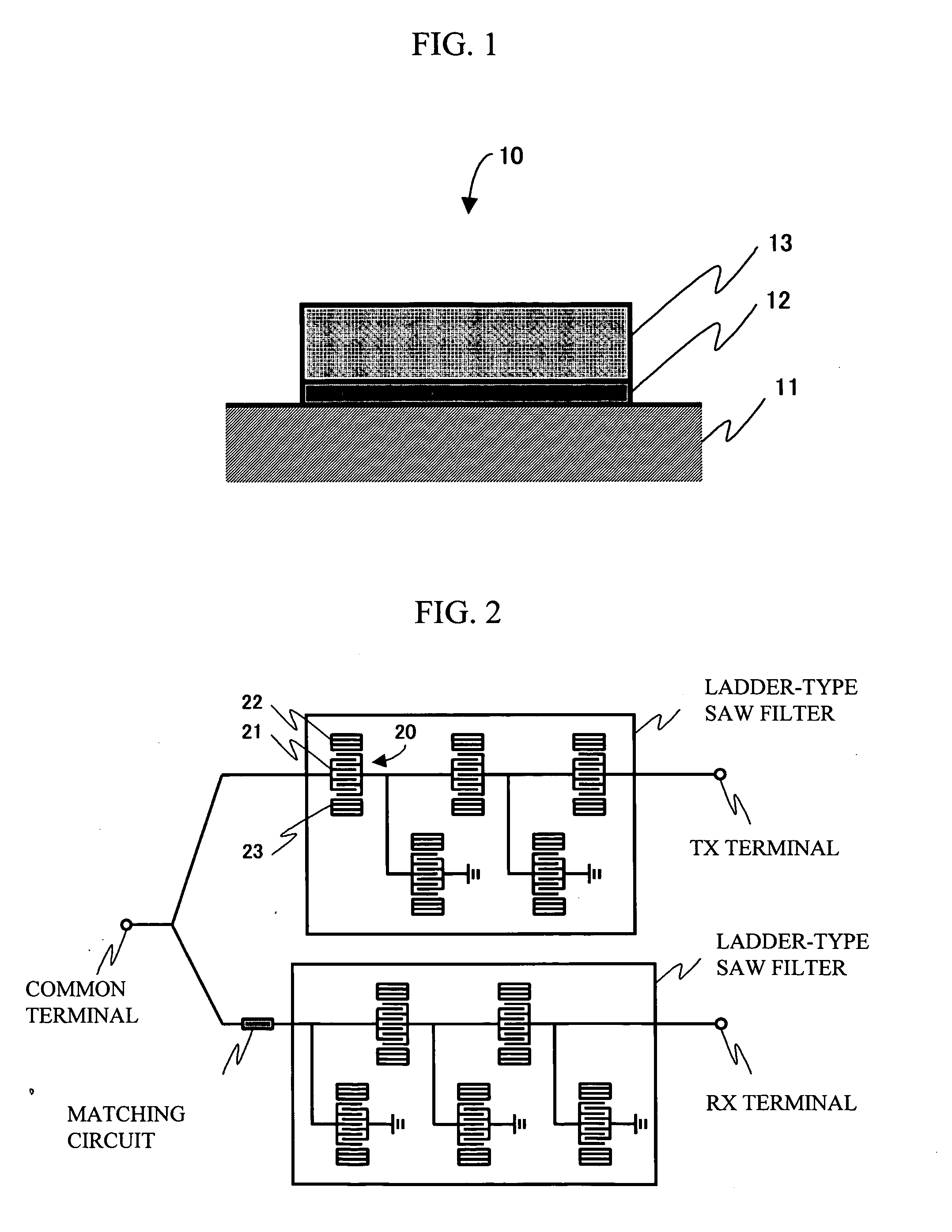
[0047] The first embodiment is a ladder-type SAW filter that has four stages and a 1.9 GHz pass band and employs a 42° Y-cut X-propagation LiTaO3 substrate. The electrode of this filter has the double-layered structure of Al-0.15 wt % Ti / Ti, and the Ti underlying film has a thickness ratio of 24 percent. For comparison, there is provided another ladder-type SAW filter that includes the conventional electrode having the upper film of Al-0.5 wt % Cu. These filters were produced by a continuous one-time RIE process without changes of the RIE conditions on the upper film and the Ti underlying film.
[0048]FIG. 8 is a graph showing the results of evaluation of the power durability of the above two ladder-type SAW filters having four stages. The horizontal axis of FIG. 8 denotes the electric power (W) applied to the high-frequency edge of the 3 dB pass band. The vertical axis denotes the time (life: h) in which the 3 dB pass band width is degraded by only five percent with the aforemention...
second embodiment
[0049] The second embodiment is a ladder-type SAW filter has four stages and an 800 MHz pass band and employs a 42° Y-cut X-propagation LiTaO3 substrate. The electrode of this filter is the double-layered structure of Al-0.15 wt % Ti-0.3 wt % Cu / Ti, and the Ti underlying film has a thickness ratio of 42 percent. For comparison, there is provided another ladder-type SAW filter that includes the conventional electrode having the upper film of Al-0.5 wt % Cu. These filters were produced by a continuous one-time RIE process without changes of the RIE conditions on the upper film or the Ti underlying film.
[0050]FIG. 9 is a graph showing the results of evaluation of the power durability of the above two ladder-type SAW filters having four stages. The vertical axis of FIG. 9 denotes the time (life: h) in which the 3 dB pass band width is degraded by only five percent while the power (constant wave) is being applied to the high-frequency edge of the 3 dB pass band. As shown in FIG. 9, the ...
third embodiment
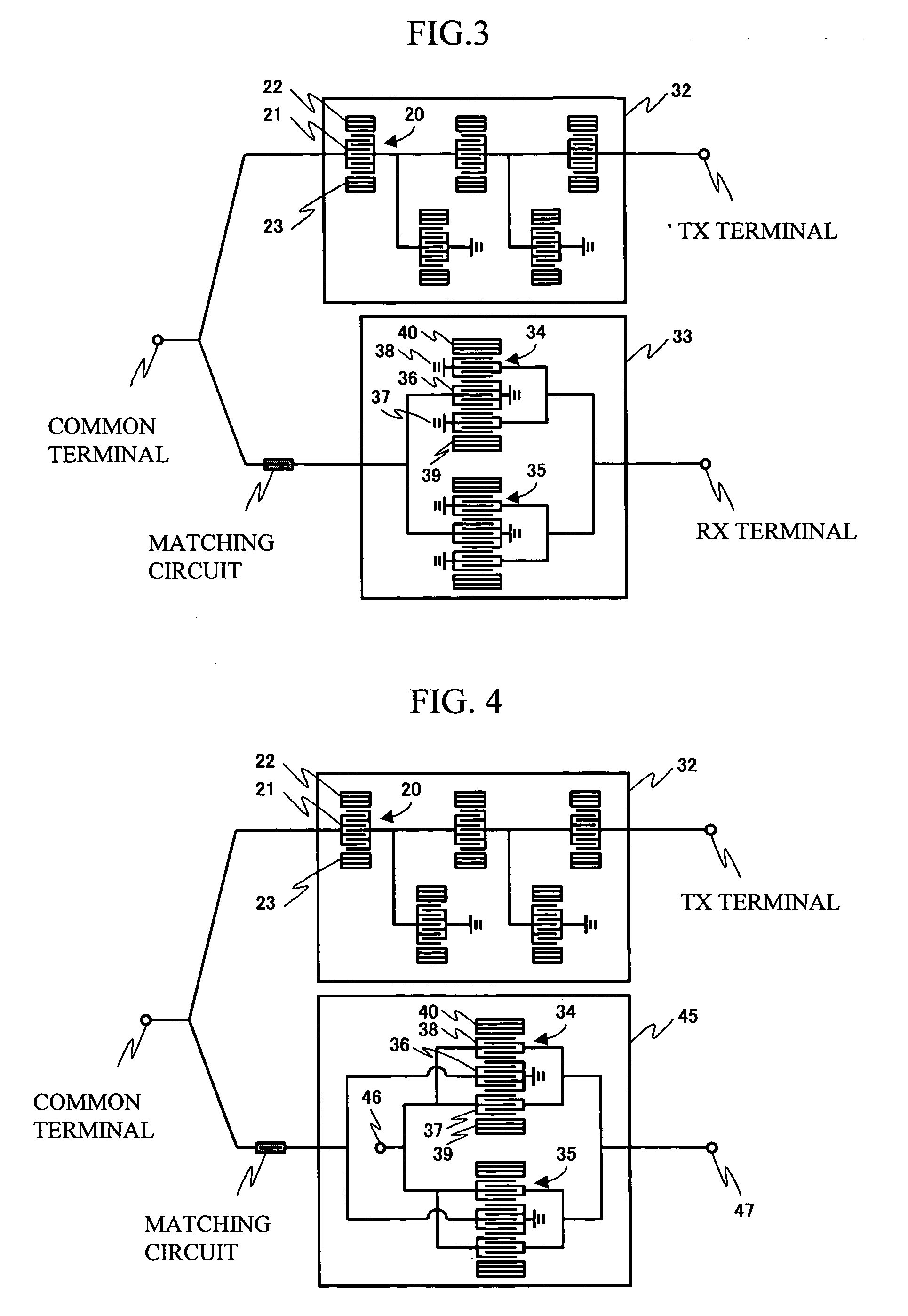
[0051] The third embodiment is a multimode SAW filter having a 1.9 GHz pass band and employs a 42° Y-cut X-propagation LiTaO3 substrate. The electrode of this filter is the double-layered structure of Al-0.15 wt % Ti0.5 wt % Cu / Ti, and the Ti underlying film has a thickness ratio of 24 percent. For comparison, there is provided another multimode SAW filter that includes the conventional electrode having the upper film of Al1 wt % Cu. These filters were produced by a continuous one-time RIE process without changes of the RIE conditions on the upper film or the Ti underlying film.
[0052]FIGS. 10A and 10B are transmission electron microscope images (TEM images) showing cross-sectional areas of the electrodes included in the two different multimode SAW filters. More specifically, FIG. 10A is a cross-sectional TEM image of the electrode having the double-layered structure of Al-0.15 wt % Ti-0.5 wt % Cu / Ti included in the multimode SAW filter in accordance with the present embodiment of t...
PUM
 Abstract
Description
Claims
Application Information
 - R&D
- Intellectual Property
- Life Sciences
- Materials
- Tech Scout
- Unparalleled Data Quality
- Higher Quality Content
- 60% Fewer Hallucinations
Browse by: Latest US Patents, China's latest patents, Technical Efficacy Thesaurus, Application Domain, Technology Topic, Popular Technical Reports.
© 2025 PatSnap. All rights reserved.Legal|Privacy policy|Modern Slavery Act Transparency Statement|Sitemap|About US| Contact US: help@patsnap.com


