Remote controller

Inactive Publication Date: 2005-12-01
ELAN MICROELECTRONICS CORPORATION
View PDF7 Cites 80 Cited by
  • Summary
  • Abstract
  • Description
  • Claims
  • Application Information

AI Technical Summary

Benefits of technology

[0008] It is yet another aspect of the present invention

Problems solved by technology

Though remote controllers have the advantages of simple operation and low cost, they can only be operated with realistic keys and are thus limited for operational functions and other applications.
However, complicated operations of pressing the realistic keys keep users from using them.
Moreover, users can only select programs or items from a fix

Method used


Image

  • Remote controller
  • Remote controller
  • Remote controller

Examples


Embodiment Construction

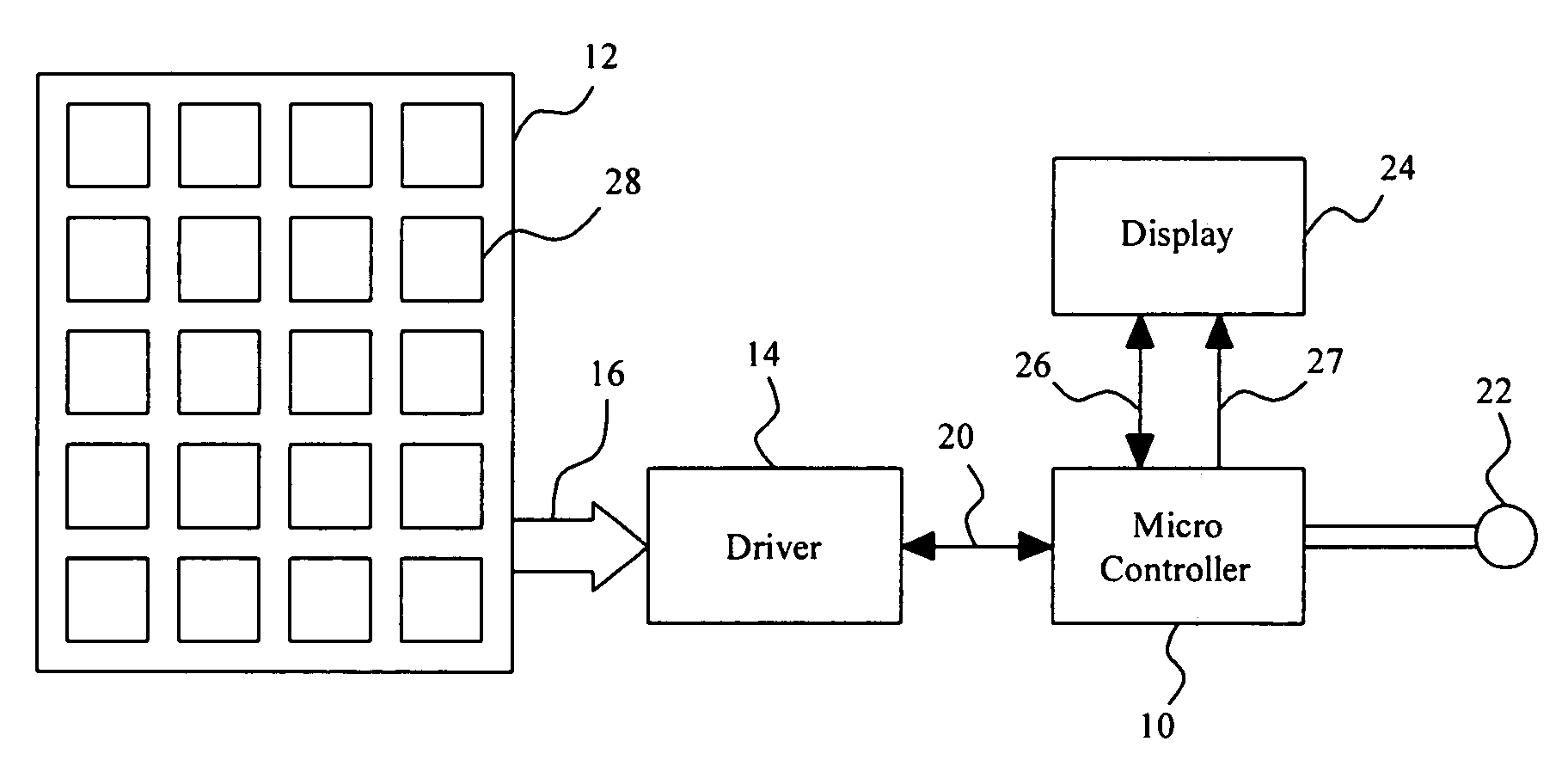
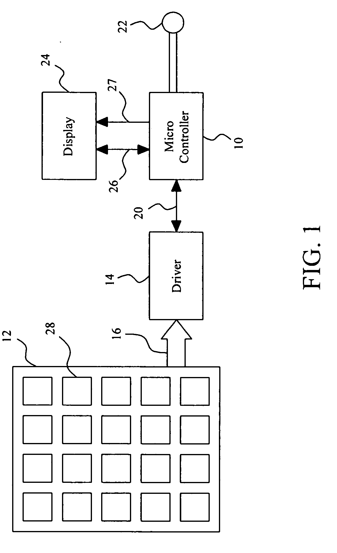
[0024]FIG. 1 shows an embodiment of a remote controller according to the present invention, which comprises a microcontroller 10 coupled with a touchpad 12 by a driver 14. The touchpad 12 may be a capacitive touchpad or a resistive touchpad, and it is used to generate an input signal 16 in response to operations thereon. In response to the input signal 16, the driver 14 asserts address data or a data signal 20 to the microcontroller 10. The microcontroller 10 is coupled with a signal generator 22 that is used to generate a remote control signal for operating a controlled apparatus in accordance with the input signal 16 or the operations on the touchpad 12. In other embodiments, the driver 14 and the microcontroller 10 can be integrated together. The specific circuitry of the driver 14 depends on the type of the touchpad 12, e.g., a capacitive touchpad or a resistive touchpad. In this embodiment, the driver 14 is used to drive the touchpad 12 and to transform the electronic signal 16...


PUM


Abstract

A remote controller comprises a touchpad having a handwriting region to be operated to generate an input signal, a driver coupled with the touchpad, and a microcontroller coupled with the driver to respond to the input signal to generate a control signal for a controlled apparatus, so as to give a command to the controlled apparatus, or to name a file or to search a file on the controlled apparatus. On the touchpad, several key patterns may be provided or one or more regions may be arranged, to provide various input functions of key mode, mouse mode, scroll mode or graphic mode.

Description

FIELD OF THE INVENTION [0001] The present invention is related generally to a remote controller and more particularly, to a remote controller having a touchpad for implementing input functions of the remote controller. BACKGROUND OF THE INVENTION [0002] Remote controllers have been widely used in various equipments in daily life, such as televisions (TV), video recorder / players, air-conditioners, cars, motorcycles, electric scrolling gates, lights, and projectors. Though remote controllers have the advantages of simple operation and low cost, they can only be operated with realistic keys and are thus limited for operational functions and other applications. Improvements to remote controllers have been made to expand the functionality, such as selecting a program list on a television. However, complicated operations of pressing the realistic keys keep users from using them. Moreover, users can only select programs or items from a fix list that is provided on a display, but not allowe...

Claims


Application Information

Patent Timeline
IPC IPC(8): G06F3/033G06F3/048G09G5/00H04B10/04
CPCG06F3/03547H04N21/42661G06F3/04886G06F3/0485
Inventor YEH, I-HAU
Owner ELAN MICROELECTRONICS CORPORATION
Why Eureka
Try Eureka