Projection-type image display apparatus

Inactive Publication Date: 2005-12-01
KK TOSHIBA
View PDF6 Cites 59 Cited by
  • Summary
  • Abstract
  • Description
  • Claims
  • Application Information

AI Technical Summary

Benefits of technology

[0039] According to the projection-type image display apparatus of the present i

Problems solved by technology

In addition to the self-heating, reflective display devices generate heat due to a reflection loss, and transmissive display devices generate heat due to a transmission loss.
However, the arrangements are not applicable to projection-type image display apparatuses having different circuit configurations or modes.
However, since the projection-type image display apparatus disclosed in U.S. Pat. No. 6,682,197 includes the intake fan and the exhaust fan at the front left and the front right thereof, the duct structure connecting the intake fan and the exhaust fan is not linear, and includ

Method used


Image

  • Projection-type image display apparatus
  • Projection-type image display apparatus
  • Projection-type image display apparatus

Examples


Example

[0054] A first embodiment of a projection-type image display apparatus 1 according to the present invention will now be described with reference to the drawings.

(1) Overall Structure of Display Apparatus

[0055] In the projection-type image display apparatus 1, light beams from a light source such as an extra-high pressure mercury lamp are incident on a display device referred to as a DMD through a rotational film with RGB colors (color wheel). The light beams modulated in the DMD for each pixel are reflected, enlarged through a projection lens unit 6, and then projected onto a screen.

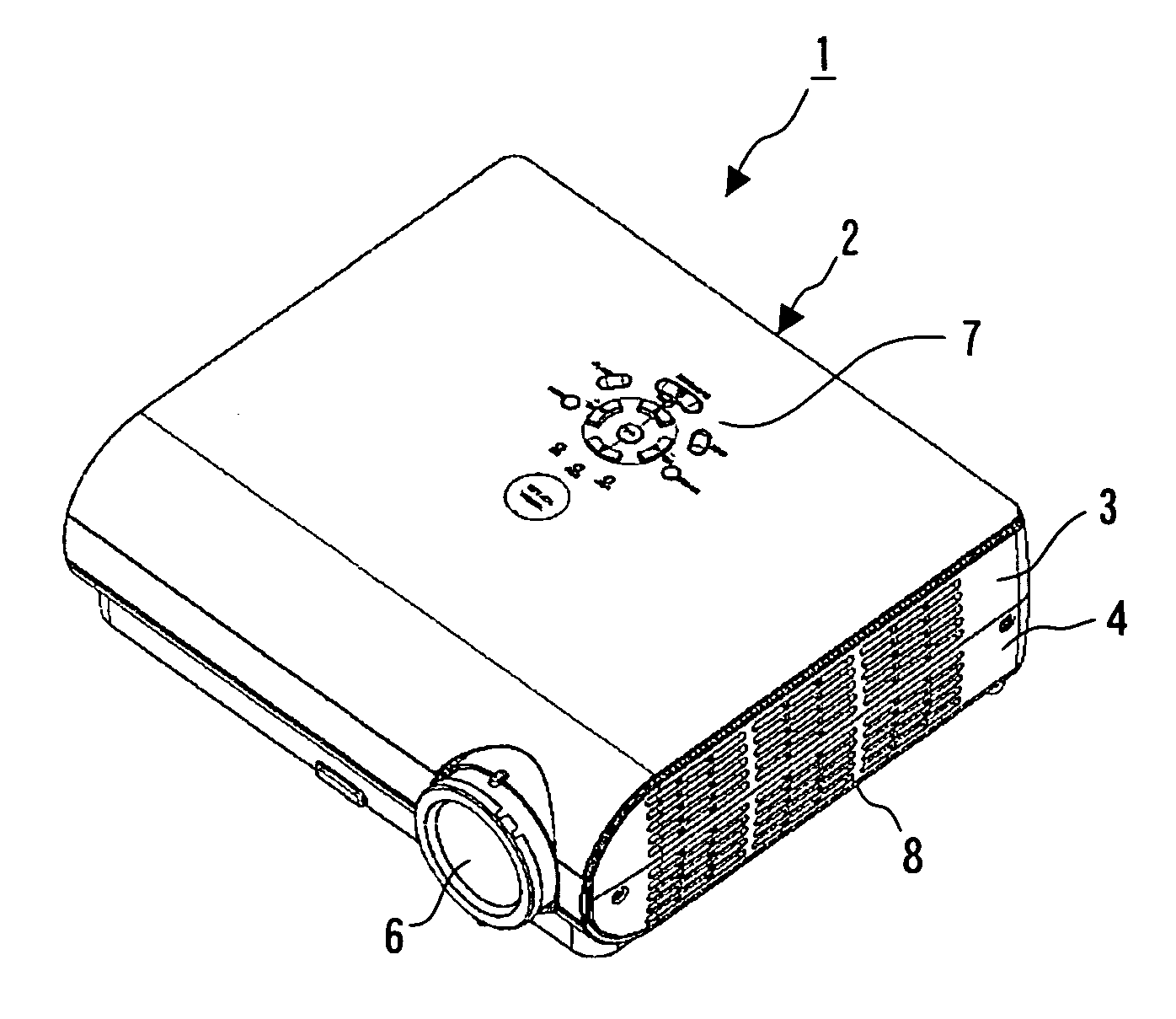
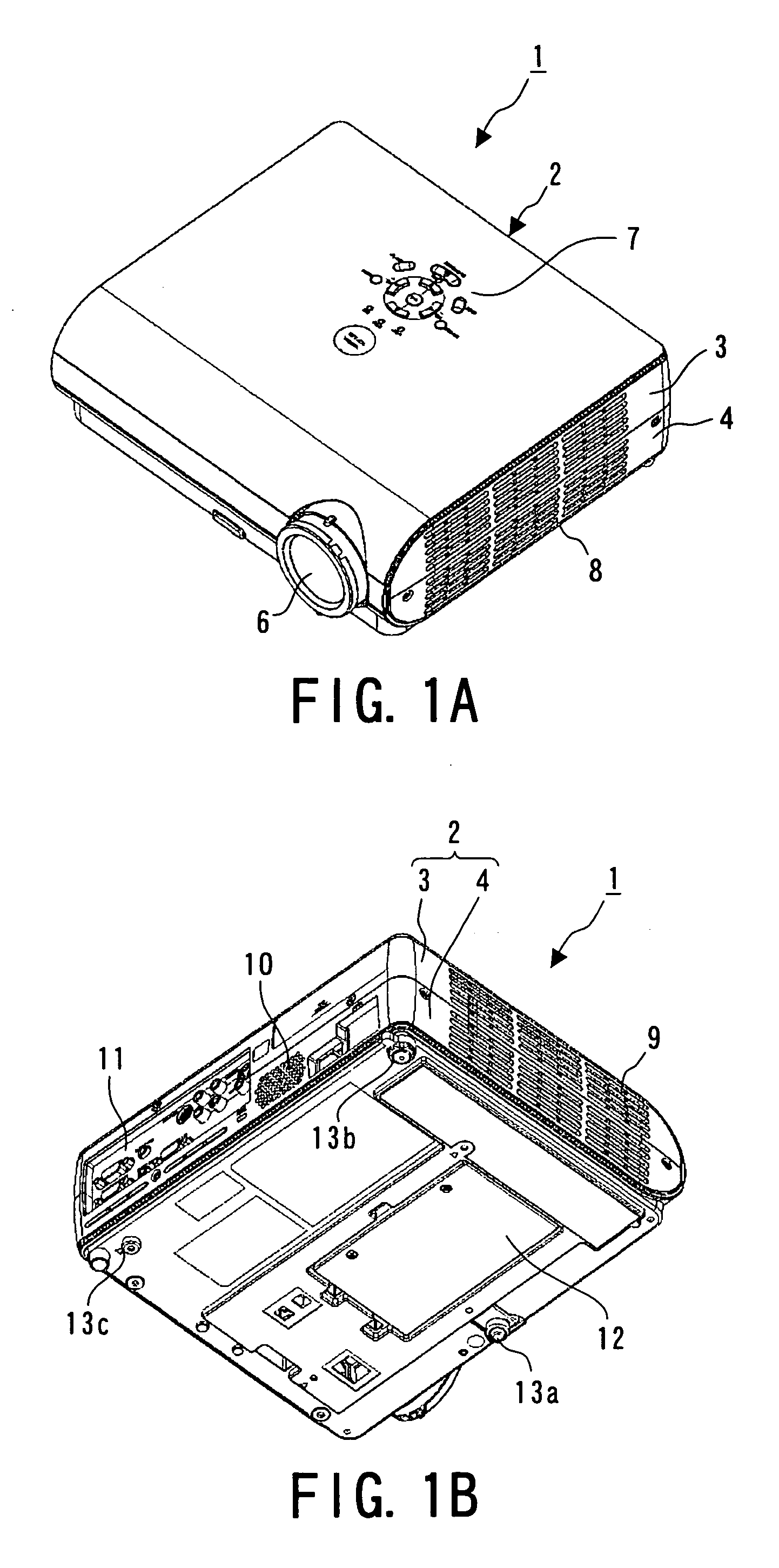
[0056]FIGS. 1A and 1B are exemplary overviews of the projection-type image display apparatus 1. FIG. 1A is a perspective view of the projection-type image display apparatus 1 shown from above, and FIG. 1B is a perspective view shown from below.

[0057] With reference to FIGS. 1A and 1B, the projection-type image display apparatus 1 includes a body casing 2 separable into two portions (upper and lower)...

Example

(8) Second Embodiment

[0158] According to the first embodiment, the housing 202 is substantially sealed, and as a result, the cooling air passing through the second flow channel 51 can be used for cooling the light-source lamp 201 without any loss of the volume.

[0159] However, the temperature of the air after cooling the light-source lamp 201 is considerably increased, and the heat may annoy an audience or the like adjacent to the air outlets 9 of the body casing 2.

[0160] According to a second embodiment, an air intake vent 209 is formed at a side surface of a housing 202 of a lamp unit 20A as shown in FIG. 13.

[0161] The air inside a body casing 2 is drawn from the air intake vent 209 to the interior of the housing 202. Since the high-temperature air inside the housing 202 is mixed with the low-temperature air drawn from the interior of the body casing 2, the temperature of the air discharged from air outlets 9 is reduced so as not to annoy an audience or the like.

[0162] The po...


PUM


Abstract

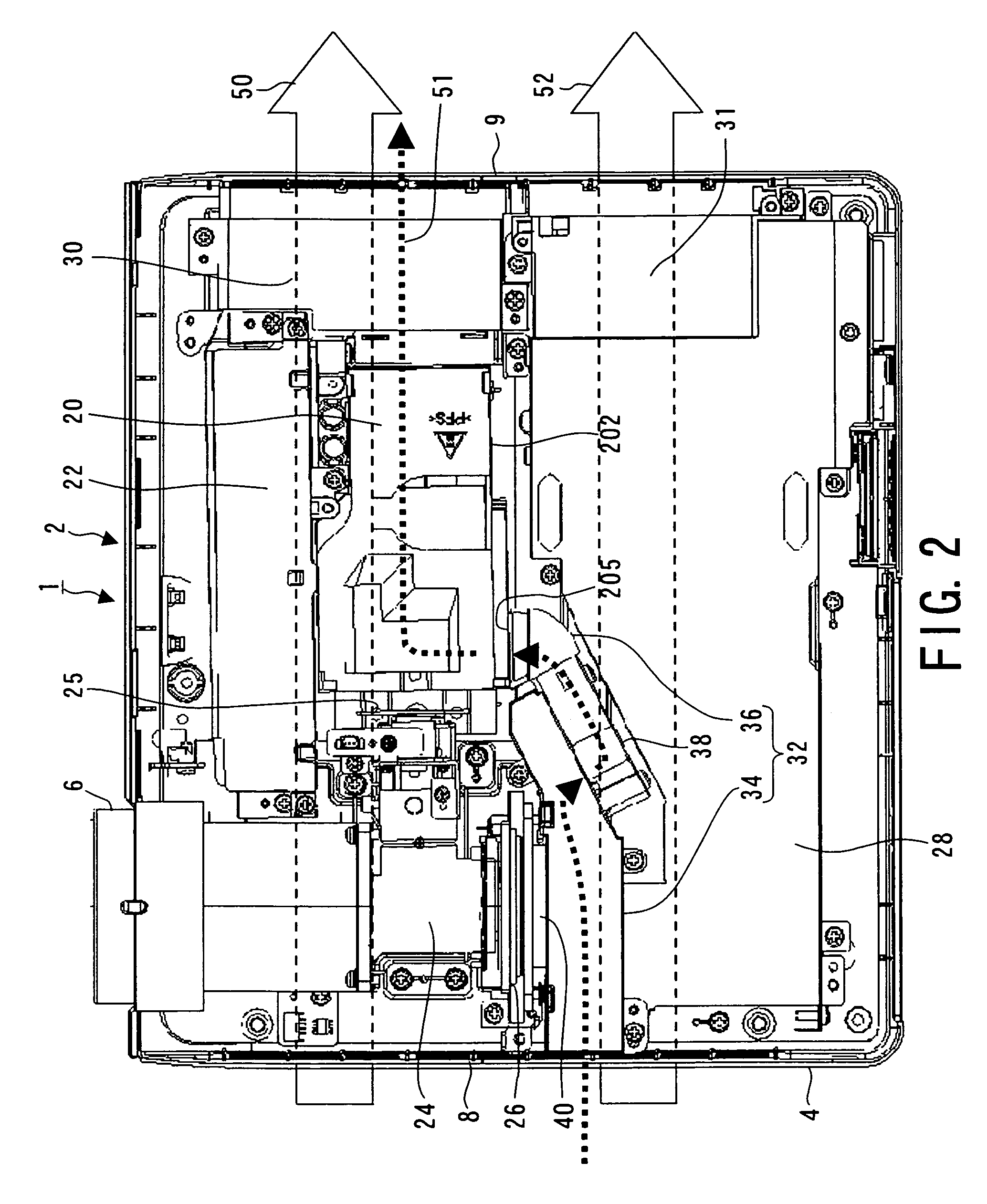
A projection-type image display apparatus includes a body including an air inlet and an air outlet and accommodating a heating element; a lamp unit including a light-source lamp and a housing that accommodates the light-source lamp and that includes an air intake and an exhaust opening communicating with the air outlet; a duct unit including a first end adjacent to the air inlet, a second end adjacent to the air intake, and a flow channel connecting the first and second ends; a radiating unit thermally connected to the heating element, at least part of the radiating unit being disposed inside the flow channel of the duct unit; and a fan, drawing air from the air inlet through the first end of the duct unit and sending the air to the air intake through the second end, disposed between the radiating unit and the second end.

Description

CROSS-REFERENCE TO RELATED APPLICATIONS [0001] This application claims the benefit of priority of Japanese Patent Application No. 2004-162485, filed May 31, 2004, the entire contents of which are incorporated herein by reference. BACKGROUND [0002] 1. Field [0003] The present invention relates to projection-type image display apparatuses projecting enlarged images shown on display devices onto screens, and in particular, relates to projection-type image display apparatuses including structures for cooling the display devices, light-source lamps, or the like. [0004] 2. Description of the Related Art [0005] Projection-type image display apparatuses enlarge images shown on display devices such as small cathode-ray tubes (CRTs) or light valves (small display devices capable of storing and removing the images in real time) through projection lenses and project the images onto screens. [0006] Among such display devices, liquid-crystal devices as well as the small CRTs are in widespread use...

Claims


Application Information

Patent Timeline
IPC IPC(8): G03B21/00G03B21/16
CPCG03B21/00G03B21/005
Inventor MORIMOTO, TERUYUKIYAMADA, KAZUHIROKANAI, HIDEO
Owner KK TOSHIBA
Why Eureka
Try Eureka