Drop-light apparatus

Inactive Publication Date: 2005-12-01
NAT ELECTRIC MFG
View PDF12 Cites 6 Cited by
  • Summary
  • Abstract
  • Description
  • Claims
  • Application Information

AI Technical Summary

Benefits of technology

[0008] As will be seen, the housing typically has a forward illumination portion, a rearward grip portion and an intermediate portion, and wherein the lamp or lamps are carried at said forward portion, one of said two magnetic ballasts is carried at said intermediate portion, and the other of said two ballasts is carried at said rearward portion, enhancing weight distribution and ease of handling. Magnetic ballasts are significant weight adding devices, and their separation adds to manual control. One ballast may control one lamp, and the other ballast may control a second lamp, whereby at least one lamp will remain energized by a ballast if the other ballast fails. The lamps are typically fluorescent.
[0009] Another object is to provide improved cushioning supports for the multiple, elongated, parallel lamps.

Problems solved by technology

Magnetic ballasts are significant weight adding devices, and their separation adds to manual control.

Method used


Image

  • Drop-light apparatus
  • Drop-light apparatus
  • Drop-light apparatus

Examples


Embodiment Construction

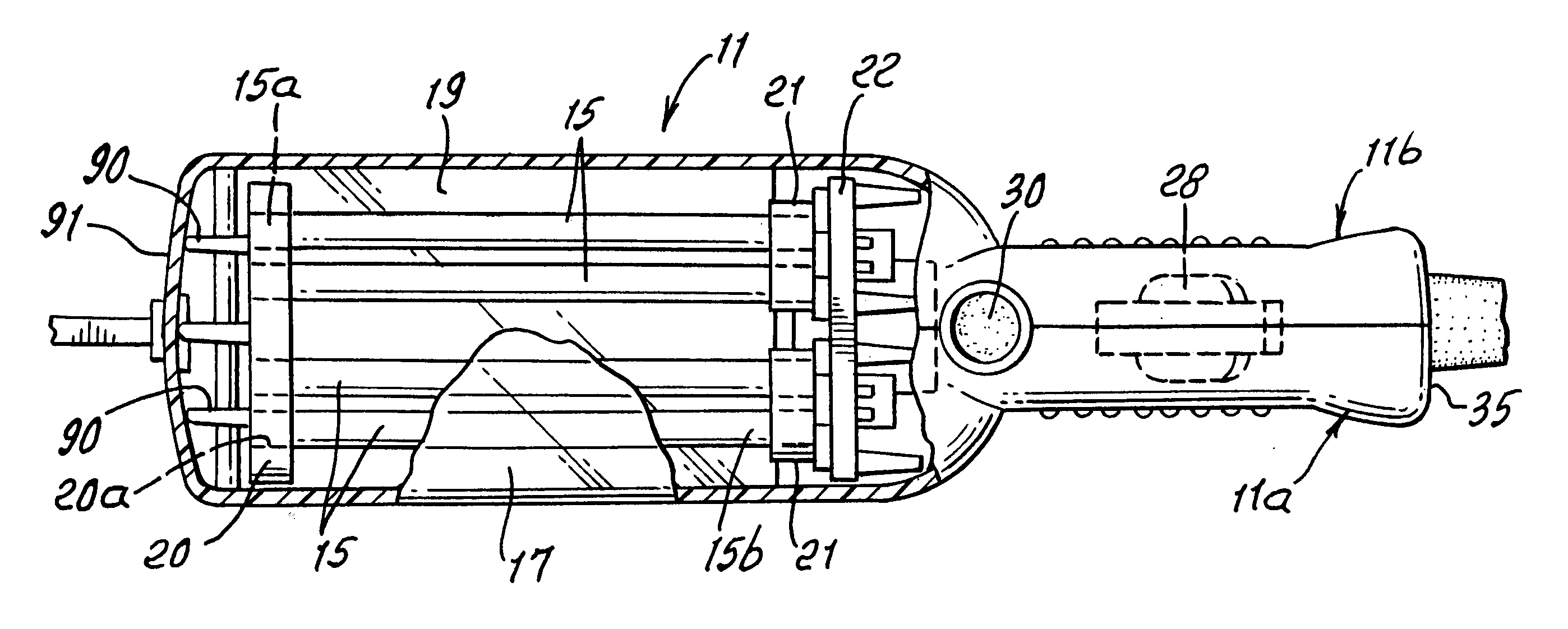
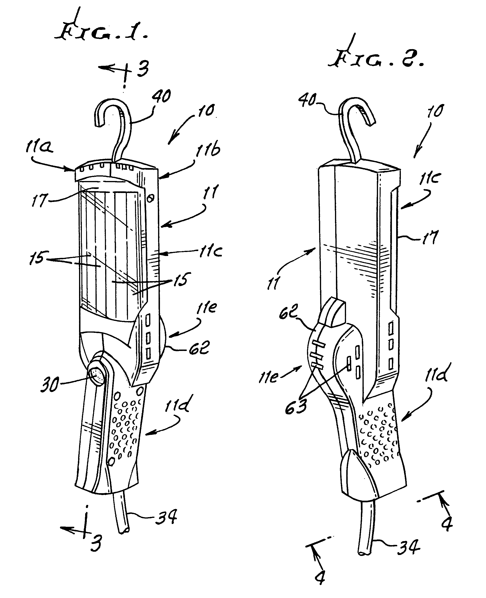
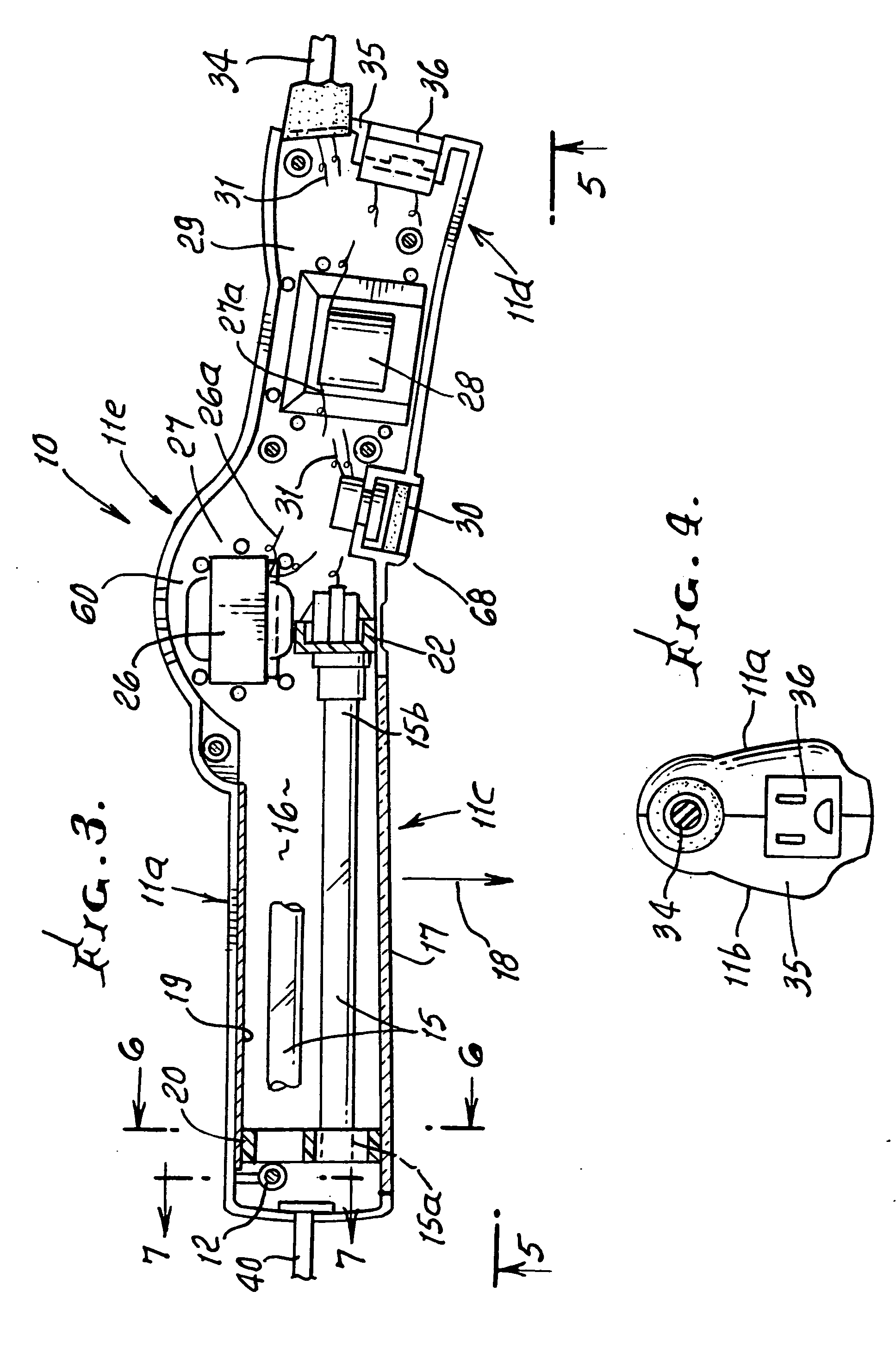
[0022] The preferred illumination device 10 includes is an elongated housing 11 which may consist of two complementary molded plastic shell sections 11a and 11b, each extending throughout the length of the housing.

[0023] Screw fasteners 12 hold the sections together, as for example is indicated in FIG. 7. A screw 12 interconnects two posts 13 and 14 respectively molded in and to sections 11a and 11b. The screw head is typically protectively received in a recess 13a of post 13. Section edges 11a′ and 11b′ are held together as shown. Other means to interconnect the sections may be provided.

[0024] The two sections of the housing together define a housing forward illumination portion 11c, a rearward grip portion 11d, and an intermediate portion 11e. At least two elongated lamps 15 are carried to extend endwise in the hollow interior 16 of the housing forward portion 11c, and so as to face a window or lens 17 peripherally carried by the housing sections 11a and 11b, as is also clear fo...


PUM


Abstract

An illumination device comprising, in combination an elongated housing, at least two elongated lamps extending in the housing, one or two magnetic ballasts carried in the housing to selectively energize the lamp or lamps, and switch means carried by the housing to control energization of said one or two ballasts.

Description

BACKGROUND OF THE INVENTION [0001] This invention relates generally to portable illumination devices and more particularly to an improved device wherein a bulb or lamp, or lamps, are energized by magnetic ballast or ballasts. [0002] There is need for improvements in portable illumination devices wherein complexity of electrical circuitry required for power supply to lamps is reduced, and wherein unreliability of such power supply is also reduced. There is also need for an improved device employing magnetic ballast or ballasts, as well as a device having improvements in structure and functions as will be seen. SUMMARY OF THE INVENTION [0003] It is a major object of the invention to provide for improvements in portable illumination devices as referred to. Basically, the device comprises: [0004] a) an elongated housing, [0005] b) at least two elongated lamps extending in the housing, [0006] c) one or preferably two magnetic ballasts carried in the housing to selectively energize the la...

Claims


Application Information

Patent Timeline
IPC IPC(8): F21L14/02F21V15/04F21V19/00F21V21/088F21V23/02F21V23/04
CPCF21L14/026F21V15/04F21V23/0414F21V21/088F21V23/02F21V19/008F21Y2103/00F21Y2113/00
Inventor GALVEZ, JAMES M.
Owner NAT ELECTRIC MFG
Why Eureka
Try Eureka