Device for monitoring an area of coverage on a work tool

a technology for work tools and monitoring devices, which is applied in the direction of metal-working feeding devices, metal-working storage devices, positioning devices, etc., can solve the problems of only monitoring the danger zone, affecting the safety of workers,

Active Publication Date: 2005-12-01
LEUZE LUMIFLEX GMBH & CO KG
View PDF13 Cites 22 Cited by
  • Summary
  • Abstract
  • Description
  • Claims
  • Application Information

AI Technical Summary

Benefits of technology

[0009] It is the goal of the present invention to create a system that allows a secure monitoring of the danger zones on working means, and which covers these danger zones as completely as possible.
[0011] One essential advantage of the device according to the invention is that by using the camera and evaluating the output signals from the receiving elements, it is not only possible to check for the presence of objects, but also to obtain depth information as a result of the distance measurements carried out. A two-dimensional image of objects within the area of coverage is obtained in this way. It is particularly advantageous that an object can be detected within the area of coverage without necessitating a reference image comparison. In particular, it is also possible to securely detect objects before a background, wherein the object detection is largely independent of environmental influences such as the structure of the background or external light irradiation.
[0012] The device according to the invention can be used, in particular, for monitoring danger zones on machines where a first machine part executes operating movements toward a second machine part. Machines of this type, in particular, can be designed as cutting or punching machines and can furthermore be embodied as bending and folding presses, wherein the first machine part is an upper tool which can be displaced relative to a stationary lower tool that forms the second machine part. It is advantageous that when the device according to the invention is installed in the region of the first machine part, the upper tool in the case of a bending press, the complete danger zone up to the lower tool can be monitored. It is particularly advantageous that movements of the work pieces to be processed do not result in blocking the beam path for the device according to the invention. Thus, object detection by means of the device is ensured within the area of coverage, even when guiding work pieces in the danger zone.
[0015] Data relating to the contours and, if necessary, also the paths of non safety-critical objects of this type are advantageously acquired in a learning process. During the operating phase following this learning process, all objects not corresponding to the acquired, non safety-critical objects are then classified as safety-critical objects, so that their detection within the area of coverage leads to a deactivation of the work tool. This ensures a maximum degree of safety for monitoring the area of coverage because only the previously acquired non safety-critical objects do not result in a deactivation of the work tool when they enter the area of coverage.
[0017] Alternatively, protective zones and non safety-critical regions can also be defined within the area of coverage, wherein only objects detected in the non safety-critical regions do not result in deactivating the work tool. By screening regions in this way, the availability of the work tool is increased because unnecessary idle times resulting from shutdown commands due to object detections in these regions are avoided.

Problems solved by technology

Work tools of this type generally are systems such as machines, plants or vehicles, and their operating movements can endanger persons within a danger zone.
This protective device has the disadvantage that a danger zone can only be monitored in points along the beam axes of the transmitting light beams for the light barriers.
This is a problem, in particular, if small object sizes must also be detected, e.g., a finger on a hand or the like, to ensure adequate protection of persons.
A further disadvantage is that the light barriers must be adjusted to be at a safe distance relative to the first machine part for monitoring the chosen danger zone, an operation that is involved and time-consuming.

Method used


Image

  • Device for monitoring an area of coverage on a work tool
  • Device for monitoring an area of coverage on a work tool
  • Device for monitoring an area of coverage on a work tool

Examples


Embodiment Construction

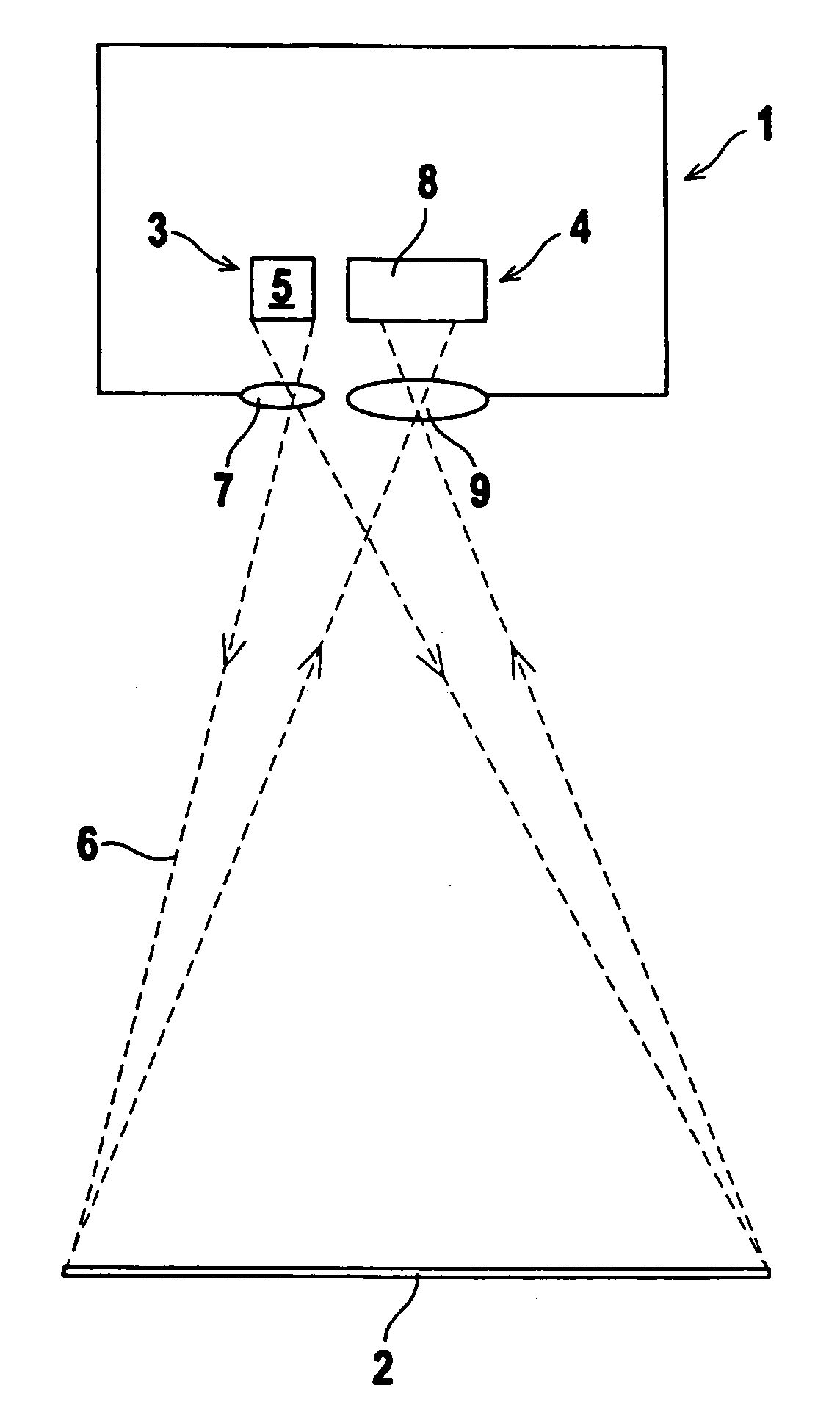
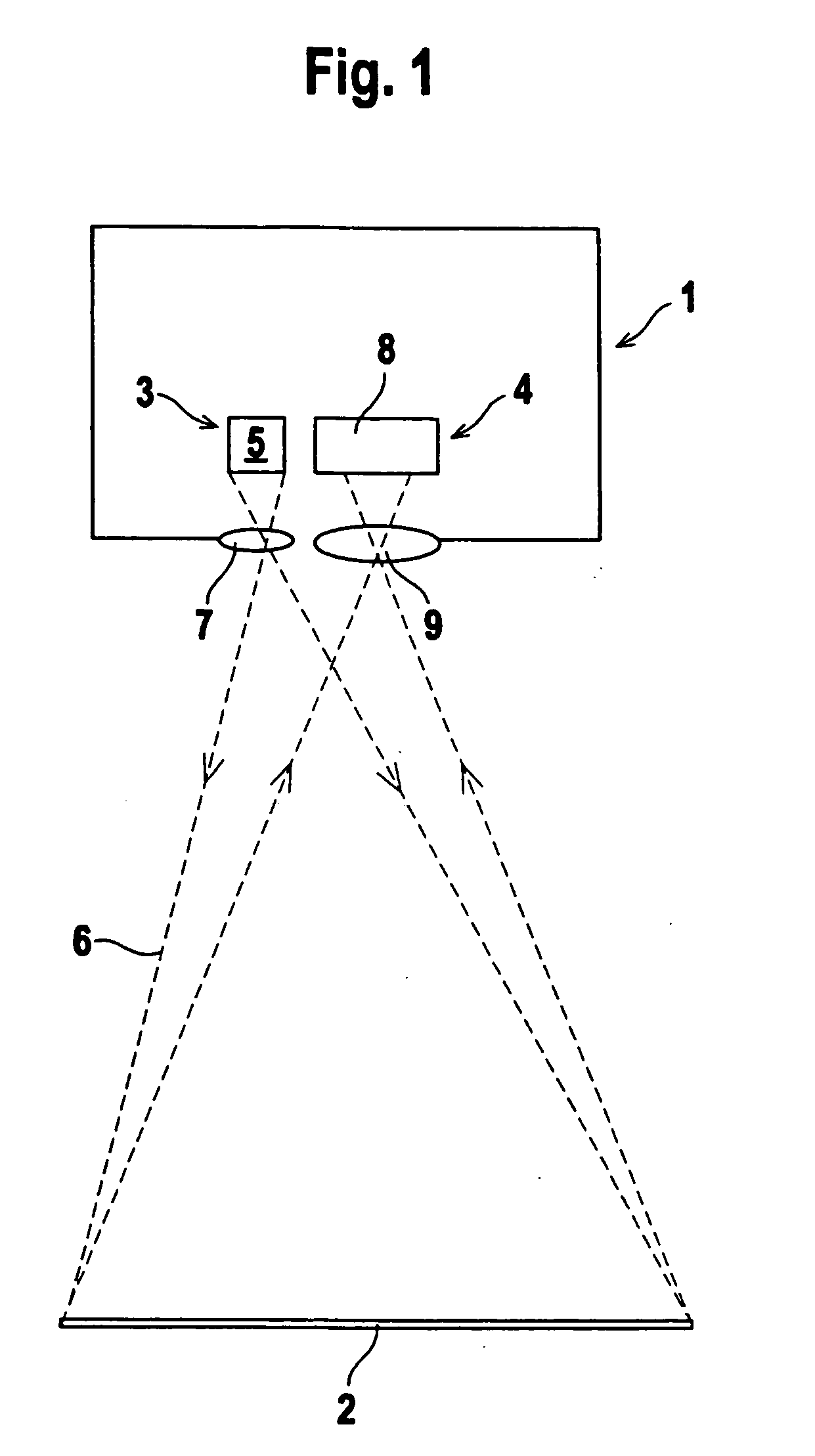
[0024]FIG. 1 schematically shows the optical components of a device 1 for monitoring an area of coverage 2 on a work tool which is not shown in FIG. 1, and which is a machine, a system, or the like, according to an embodiment of the invention. A danger zone is created in the region of the work tool as a result of operating movements carried out by the work tool. This danger zone within the area of coverage 2 is monitored by the device 1.

[0025] The optical components of the device 1 form a sensor unit, comprising a lighting unit 3 and a camera 4. For the present case, the lighting unit 3 is provided with a transmitter 5 in the form of a laser diode which emits light rays 6. Alternatively, the transmitter 5 can also be a light-emitting diode. The lighting unit 3 can furthermore also comprise arrangements of several laser diodes or light-emitting diodes. A further component of the lighting unit 3 is transmitting optics 7, installed downstream of the transmitter 5. The transmitting opt...


PUM

PropertyMeasurementUnit
areaaaaaaaaaaa
distanceaaaaaaaaaa
phase-aaaaaaaaaa

Abstract

A device for monitoring an area of coverage on a work tool may comprise a lighting unit, a camera, and an evaluation unit. The lighting unit may be adapted to emit light rays for illuminating the area of coverage. The camera may be adapted to detect two-dimensional images of the area of coverage, and the camera may comprise receiving elements arranged linearly. The evaluation unit may be coupled to the camera to evaluate the output signals of the receiving elements to determine a distance value for each receiving element based on the light rays emitted by the lighting device and reflected back from the area of coverage. The evaluation unit may have at least one switching output coupled to the work tool to activate the work tool such that the work tool is operational only if no object is located in the area of coverage.

Description

CROSS-REFERENCE TO RELATED APPLICATIONS [0001] This application is a continuation of U.S. patent application Ser. No. 11 / 020,012, filed Dec. 23, 2004, which claims the priority of German Patent Application No. 103 60 789.7-52, filed Dec. 23, 2003, the disclosures of both of which are incorporated herein by reference.BACKGROUND OF THE INVENTION [0002] The invention relates to a device for monitoring an area of coverage on a work tool. [0003] Work tools of this type generally are systems such as machines, plants or vehicles, and their operating movements can endanger persons within a danger zone. A device as mentioned in the above is used to secure such a danger zone by preventing objects from entering an area of coverage that provides the highest possible coverage for the respective danger zone. In particular, devices of this type are used for securing machines such as bending or folding presses, cutting machines, or punching machines. These machines comprise a first machine part whi...

Claims


Application Information

Patent Timeline
Patent Type & Authority Applications(United States)
IPC IPC(8): F16P3/14
CPCF16P3/14G01S17/026Y10S72/702F16P3/142F16P3/144G01S17/08G01S17/04
Inventor LOHMANN, LUTZ
Owner LEUZE LUMIFLEX GMBH & CO KG
Why Eureka
Try Eureka