Radial-flow heat-dissipating fan with increased inlet airflow
a heat-dissipating fan and inlet airflow technology, which is applied in the direction of liquid fuel engines, vessel construction, marine propulsion, etc., can solve the problems of insufficient blowing efficiency of the primary fan blades, insufficient heat dissipation, and insufficient heat dissipation, so as to increase the output wind pressure and increase the inlet airflow
- Summary
- Abstract
- Description
- Claims
- Application Information
AI Technical Summary
Benefits of technology
Problems solved by technology
Method used
Image
Examples
first embodiment
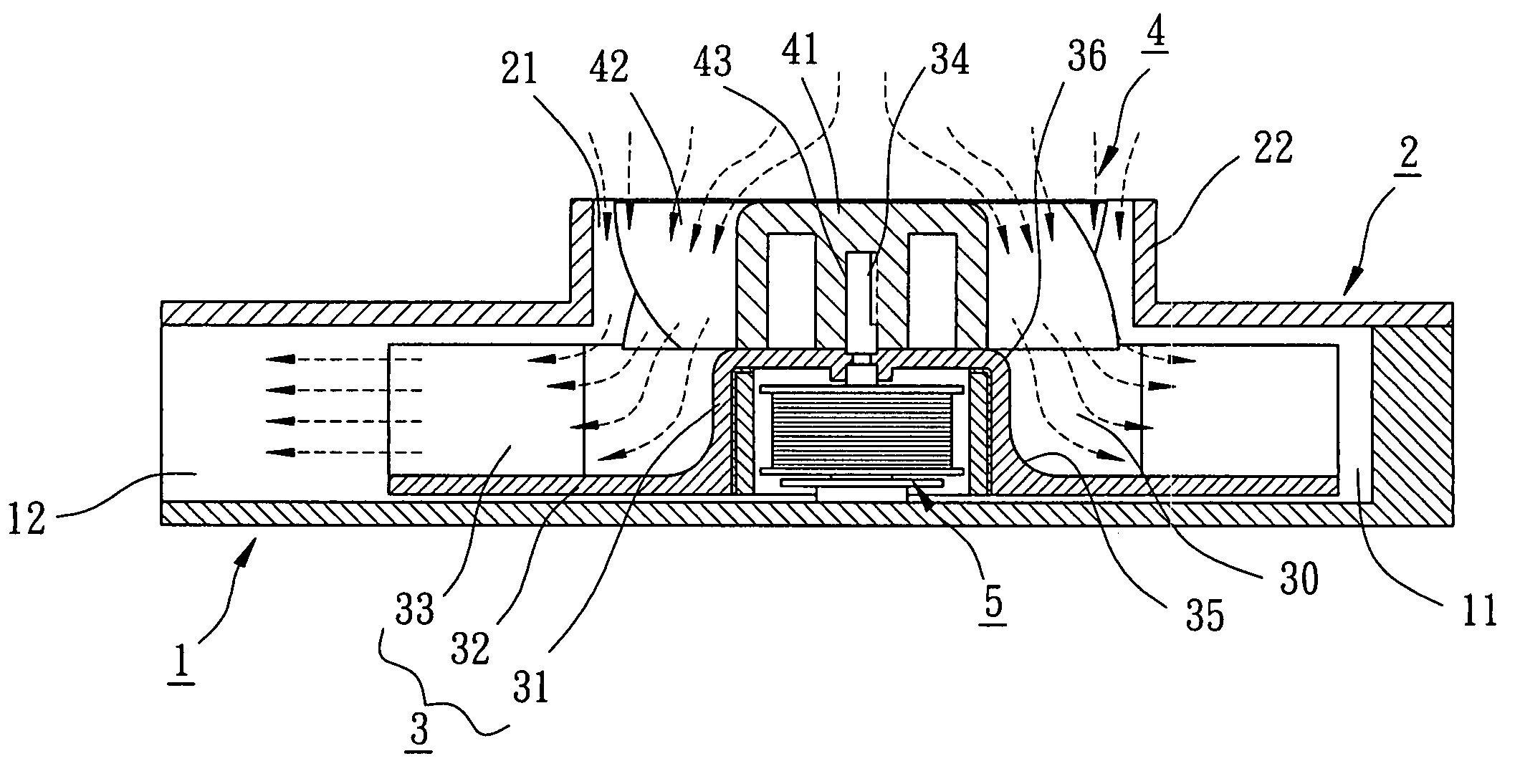
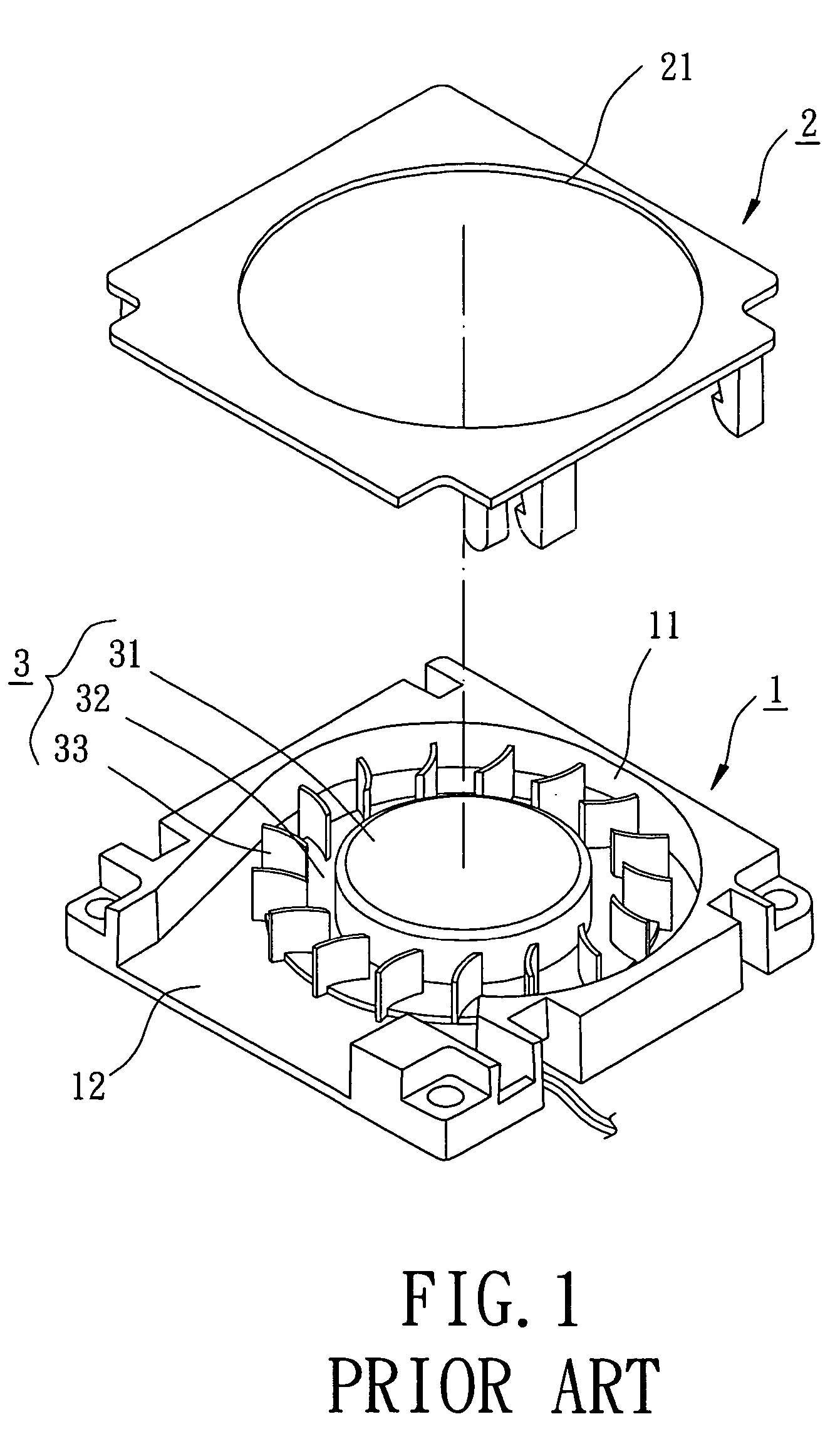
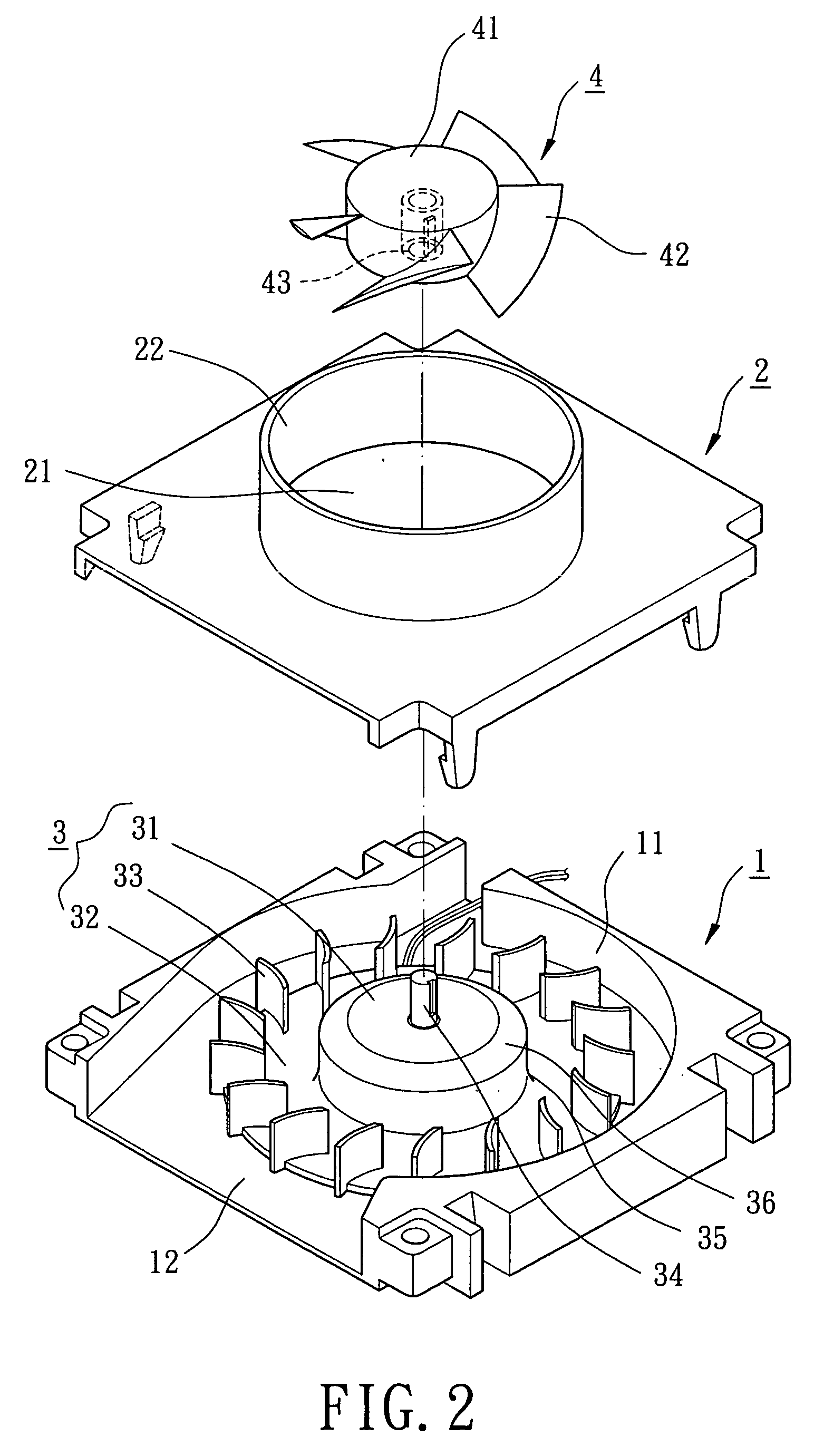
[0033] Referring to FIGS. 2 and 3, a radial-flow heat-dissipating fan in accordance with the present invention comprises a casing 1, a cover 2, a primary fan wheel 3, an auxiliary fan wheel 4, and an airflow transition area 30. The casing 1 includes a compartment 11 for rotatably receiving the primary fan wheel 3 and a side air outlet 12 that is communicated with the compartment 11 and outputs centrifugal airflow. The cover 2 is mounted to a side of the casing 1 and includes an air inlet 21. Preferably, an annular wall 22 is formed on a side of the cover 2 and extends from a periphery delimiting the air inlet 21.
[0034] The primary fan wheel 3 includes a hub 31, an annular plate 32 extending from the hub 31, and a plurality of radial-flow blades 33 formed on a side of the annular plate 32. A motor 5 is mounted inside the hub 31 and includes a shaft 34 extending beyond the hub 31. The motor 5 further includes a first guiding face 35 and a second guiding face 36. The first guiding face...
second embodiment
[0037]FIG. 4 illustrates the present invention, wherein the hub 31 of the primary fan wheel 3 includes a reduced section 37, and the hub 41 of the auxiliary fan wheel 4 includes a coupling section 44 engaged with the reduced section 37 by means of bonding, screwing, welding, snapping, or force-fitting. Further, the axial-flow blades 42 of the auxiliary fan wheel 4 extend outward from a top face of the hub 41 to a circumference of the hub 41. The axial-flow blades 42 of the auxiliary wheel 4 is at an axial height not higher than that of the cover 2. Still, an airflow transition area 30 is defined between the axial-flow fan blades 42, the radial-flow fan blades 33, the annular plate 32, the first guiding face 35, and the second guiding face 36. Similar to the above embodiment, the overall air inlet amount is increased, the direction of the incoming airflow is smoothly changed, and the blowing noise is lowered. Further, the output wind pressure is increased and the heat-dissipating eff...
third embodiment
[0038]FIG. 5 illustrates the present invention, wherein the auxiliary fan wheel 4 is driven by a motor 5′ separate from the motor 5 for driving the primary fan wheel 3. The cover 2 includes a base 23 and a plurality of ribs 24 in the air inlet 21. The auxiliary fan wheel 4 is mounted in the annular wall 22 of the cover 2, with the base 23 being supported by the ribs 24 to allow coupling of the motor 5′ and the auxiliary fan wheel 4 with the base 23. The motors 5 and 5′ can be controlled to turn at different speeds according to different heat-dissipating needs. Thus, the air inlet efficiency of the auxiliary fan wheel 4 and the air outlet efficiency of the primary fan wheel 3 can be adjusted. For example, in a case that the speed of the auxiliary fan wheel 4 is higher than that of the primary fan wheel 3, the axial-flow blades 42 of the auxiliary fan wheel 4 can be used to drive more axial airflow into the airflow transition area 30, and the radial-flow blades 33 of the primary fan w...
PUM
 Abstract
Description
Claims
Application Information
 - R&D
- Intellectual Property
- Life Sciences
- Materials
- Tech Scout
- Unparalleled Data Quality
- Higher Quality Content
- 60% Fewer Hallucinations
Browse by: Latest US Patents, China's latest patents, Technical Efficacy Thesaurus, Application Domain, Technology Topic, Popular Technical Reports.
© 2025 PatSnap. All rights reserved.Legal|Privacy policy|Modern Slavery Act Transparency Statement|Sitemap|About US| Contact US: help@patsnap.com


