Radial-flow heat-dissipating fan with increased inlet airflow

a heat-dissipating fan and inlet airflow technology, which is applied in the direction of wind motors with perpendicular air flow, waterborne vessels, machines/engines, etc., can solve the problems of insufficient blowing efficiency of the primary fan blades, insufficient inlet airflow, and insufficient inlet airflow, so as to increase the output wind pressure and increase the inlet airflow

Inactive Publication Date: 2006-11-14
SUNONWEALTH ELECTRIC MACHINE IND
View PDF6 Cites 31 Cited by
  • Summary
  • Abstract
  • Description
  • Claims
  • Application Information

AI Technical Summary

Benefits of technology

[0006]An object of the present invention is to provide a radial-flow heat-dissipating fan comprising a primary fan wheel and at least one auxiliary fan wheel for increasing inlet airflow and increasing output wind pressure.
[0007]Another object of the present invention is to provide a radial-flow heat-dissipating fan comprising a primary fan wheel and at least one auxiliary fan wheel for smoothly changing output direction of airflow, thereby lowering blowing noise.SUMMARY OF THE INVENTION
[0021]In accordance with the radial-flow heating-dissipating fan of the present invention, the overall air inlet amount is increased, the direction of the incoming airflow is smoothly changed, and the blowing noise is lowered. Further, the output wind pressure is increased and the heat-dissipating efficiency is thus improved.

Problems solved by technology

However, since the blades of the guiding fan wheel are almost in contact with the annular plate of the primary fan wheel and away from the air inlet, the inlet airflow is only increased by a relatively small amount via the air inlet.
Further, since the direction of the axial inlet airflow could not be changed in time, the inlet airflow directly impinges the annular plate of the primary fan wheel, resulting in turbulent and noise.
Further, since the blades of the guiding fan wheel are close to the blades of the primary fan wheel and thus block a portion of the blades of the primary fan wheel, the blowing efficiency of the blades of the primary fan wheel could not reach the expected result.

Method used


Image

  • Radial-flow heat-dissipating fan with increased inlet airflow
  • Radial-flow heat-dissipating fan with increased inlet airflow
  • Radial-flow heat-dissipating fan with increased inlet airflow

Examples


first embodiment

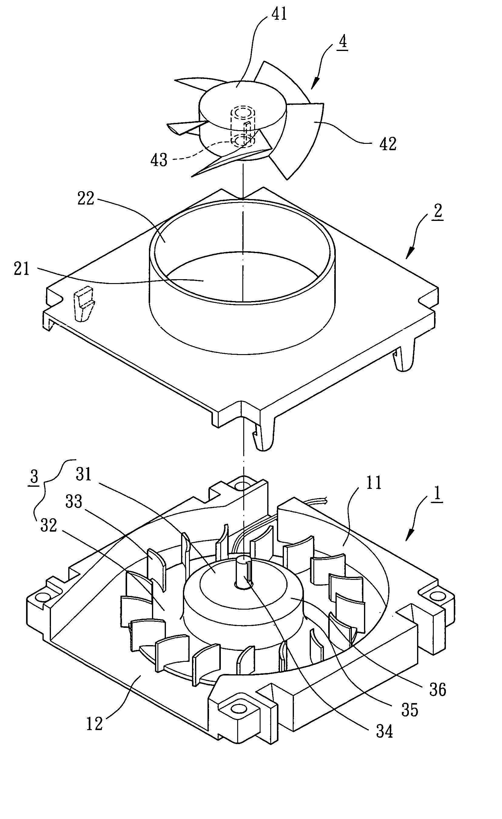
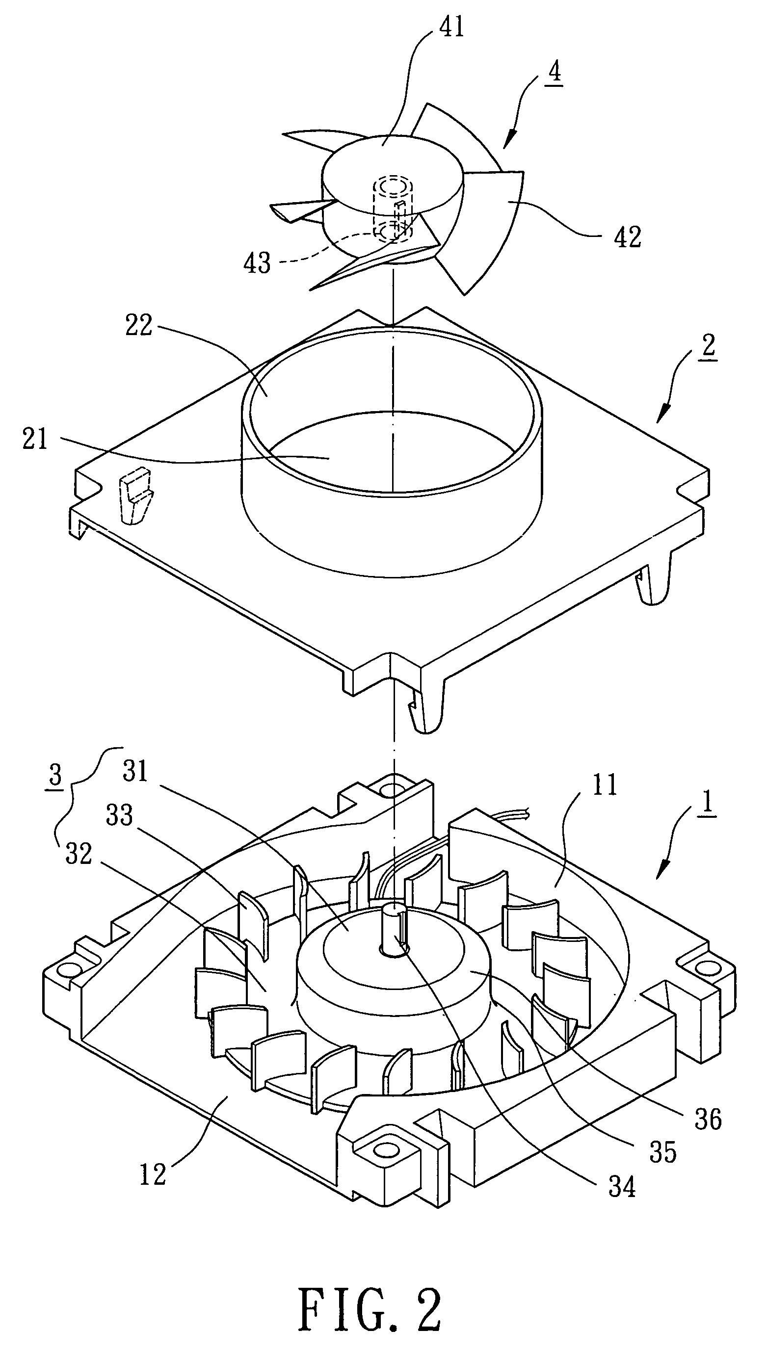
[0033]Referring to FIGS. 2 and 3, a radial-flow heat-dissipating fan in accordance with the present invention comprises a casing 1, a cover 2, a primary fan wheel 3, an auxiliary fan wheel 4, and an airflow transition area 30. The casing 1 includes a compartment 11 for rotatably receiving the primary fan wheel 3 and a side air outlet 12 that is communicated with the compartment 11 and outputs centrifugal airflow. The cover 2 is mounted to a side of the casing 1 and includes an air inlet 21. Preferably, an annular wall 22 is formed on a side of the cover 2 and extends from a periphery delimiting the air inlet 21.

[0034]The primary fan wheel 3 includes a hub 31, an annular plate 32 extending from the hub 31, and a plurality of radial-flow blades 33 formed on a side of the annular plate 32. A motor 5 is mounted inside the hub 31 and includes a shaft 34 extending beyond the hub 31. The motor 5 further includes a first guiding face 35 and a second guiding face 36. The first guiding face 3...

second embodiment

[0037]FIG. 4 illustrates the present invention, wherein the hub 31 of the primary fan wheel 3 includes a reduced section 37, and the hub 41 of the auxiliary fan wheel 4 includes a coupling section 44 engaged with the reduced section 37 by means of bonding, screwing, welding, snapping, or force-fitting. Further, the axial-flow blades 42 of the auxiliary fan wheel 4 extend outward from a top face of the hub 41 to a circumference of the hub 41. The axial-flow blades 42 of the auxiliary wheel 4 is at an axial height not higher than that of the cover 2. Still, an airflow transition area 30 is defined between the axial-flow fan blades 42, the radial-flow fan blades 33, the annular plate 32, the first guiding face 35, and the second guiding face 36. Similar to the above embodiment, the overall air inlet amount is increased, the direction of the incoming airflow is smoothly changed, and the blowing noise is lowered. Further, the output wind pressure is increased and the heat-dissipating eff...

third embodiment

[0038]FIG. 5 illustrates the present invention, wherein the auxiliary fan wheel 4 is driven by a motor 5′ separate from the motor 5 for driving the primary fan wheel 3. The cover 2 includes a base 23 and a plurality of ribs 24 in the air inlet 21. The auxiliary fan wheel 4 is mounted in the annular wall 22 of the cover 2, with the base 23 being supported by the ribs 24 to allow coupling of the motor 5′ and the auxiliary fan wheel 4 with the base 23. The motors 5 and 5′ can be controlled to turn at different speeds according to different heat-dissipating needs. Thus, the air inlet efficiency of the auxiliary fan wheel 4 and the air outlet efficiency of the primary fan wheel 3 can be adjusted. For example, in a case that the speed of the auxiliary fan wheel 4 is higher than that of the primary fan wheel 3, the axial-flow blades 42 of the auxiliary fan wheel 4 can be used to drive more axial airflow into the airflow transition area 30, and the radial-flow blades 33 of the primary fan w...


PUM


Abstract

A radial-flow heat-dissipating fan includes a casing and a cover mounted to a side of the casing. The casing includes a compartment and a side air outlet, and the cover includes an air inlet. A primary fan wheel is rotatably mounted in the compartment and the primary fan wheel includes a hub and a plurality of radial-flow blades surrounding the hub. An auxiliary fan wheel is mounted in the air inlet of the cover and includes a plurality of axial-flow blades. An airflow transition area is defined between a circumference of the hub of the primary fan wheel, the radial-flow blades, and the axial-flow blades. The axial-flow blades increase axial inlet airflow via the air inlet, with the airflow transition area changing a direction of the axial inlet airflow into centrifugal airflow that is outputted via the side air outlet by the radial-flow blades.

Description

BACKGROUND OF THE INVENTION[0001]1. Field of the Invention[0002]The present invention relates to a radial-flow heat-dissipating fan. In particular, the present invention relates to a radial-flow heat-dissipating fan with increased inlet airflow.[0003]2. Description of Related Art[0004]FIG. 1 of the drawings illustrates a conventional radial-flow heat-dissipating fan comprising a casing 1, a cover 2, and a fan wheel 3. The casing 1 includes a compartment 11 and a side air outlet 12. The cover 2 is attached to the casing 1 and includes an air inlet 21. The fan wheel 3 is rotatably received in the compartment 11 and includes a hub 31, an annular plate 32, and a plurality of blades 33. In operation, the blades 33 are turned to draw axial airflow via the air inlet 21 of the cover 2. The airflow exits the side air outlet 12 of the casing 1 for dissipating heat from an object. The amount of inlet air is limited, as only one fan wheel 3 is used. The outlet air amount and the wind pressure a...

Claims


Application Information

Patent Timeline
Patent Type & Authority Patents(United States)
IPC IPC(8): F04D17/02F03B1/00F04D25/16F04D29/28
CPCF04D29/281F04D25/166
Inventor HORNG, ALEXLU, YU-YUAN
Owner SUNONWEALTH ELECTRIC MACHINE IND
Why Eureka
Try Eureka