
Actuating means able to be activated by fluid action

a technology of actuators and actuators, applied in fluid-pressure actuators, positive displacement liquid engines, flexible member pumps, etc., can solve problems such as increased design complexity, problem of contractile hoses being pulled out of clamping gaps, and difficult to secure the connection between contractile hoses and head pieces, and achieves reliable connection and simple structure.

Inactive Publication Date: 2005-12-01
FESTO AG & CO KG
View PDF8 Cites 8 Cited by
  • Summary
  • Abstract
  • Description
  • Claims
  • Application Information

AI Technical Summary

Benefits of technology

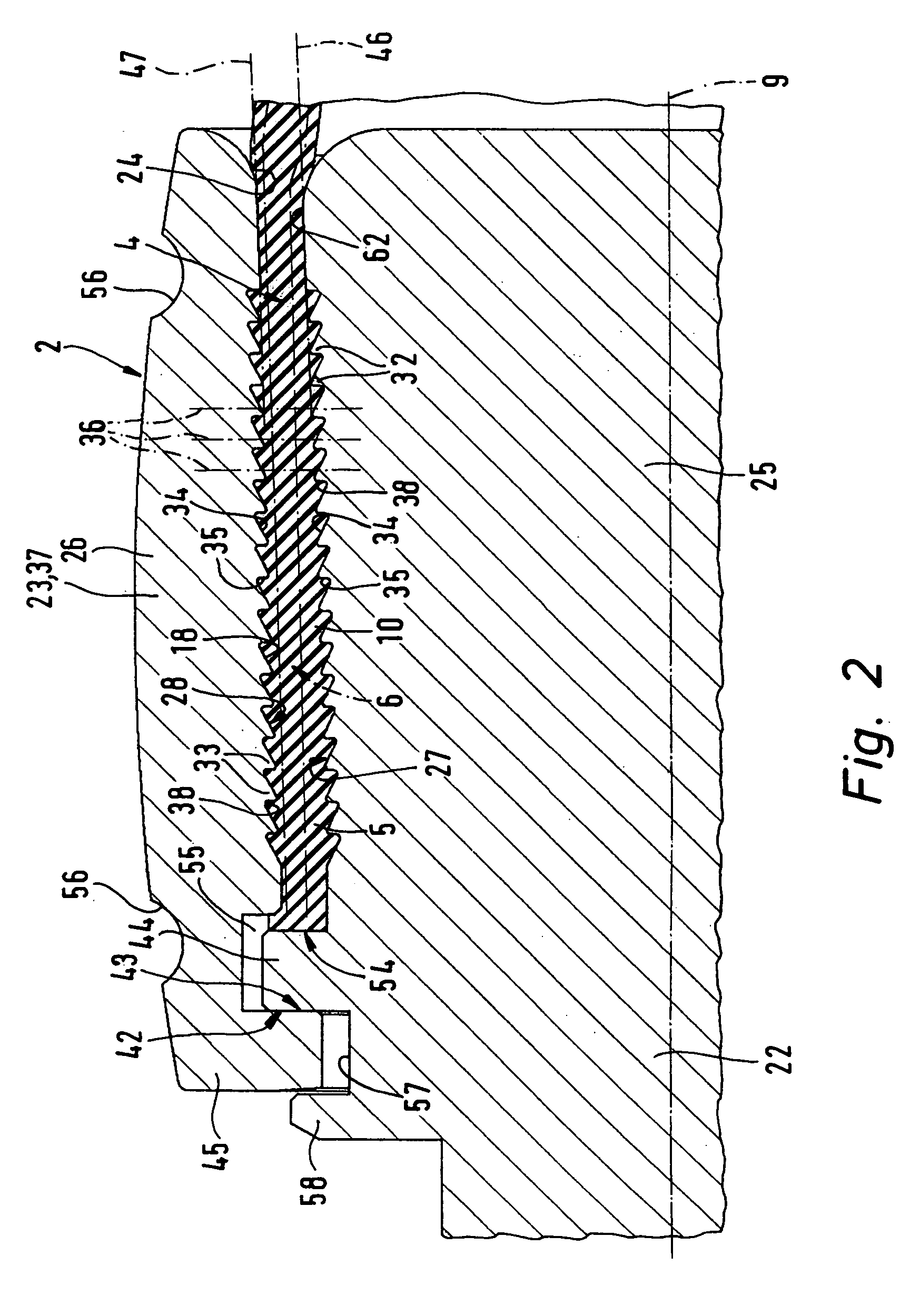
The invention is about creating an actuating means that can connect a contractile hose to a head piece with high reliability even when there is a high tension force. The invention solves this problem by using saw tooth serrated areas on the inner and outer head pieces, which bite into the elastic material of the hose body and prevent the hose from slipping out of the clamping gap. The serrated areas are arranged in a way that they oppose each other, so that even in a high tension force, the hose remains securely connected to the head piece. The compression sleeve is designed to fit over the inner head piece and can be easily adjusted to the size of the hose. The saw tooth serrated areas are positioned in parallel lines, which ensures even pressing along the entire length of the clamped hose. The invention also includes an annular gap between the inner and outer head pieces to prevent damage to the hose body during assembly. Overall, the invention provides a reliable and efficient connection between the hose and the head piece.

Problems solved by technology

This causes a radial expansion of the contractile hose resulting in a tendency to axially contract so that tension forces are applied to the head pieces, whose action on the head pieces involves moving same together.
The clamping connection between the contractile hose and the head pieces has turned out to be problematical more especially on the occurrence of substantial tension forces.
Although the clamping face of one of the clamping units is provided with several projections, which are able to bite into the material of the contractile hose, there is danger of the contractile hose's being pulled out of the clamping gap.
This design does however involve increased design complexity, something which renders manufacture more costly.

Method used


Image

  • Actuating means able to be activated by fluid action
  • Actuating means able to be activated by fluid action
  • Actuating means able to be activated by fluid action

Examples


Embodiment Construction

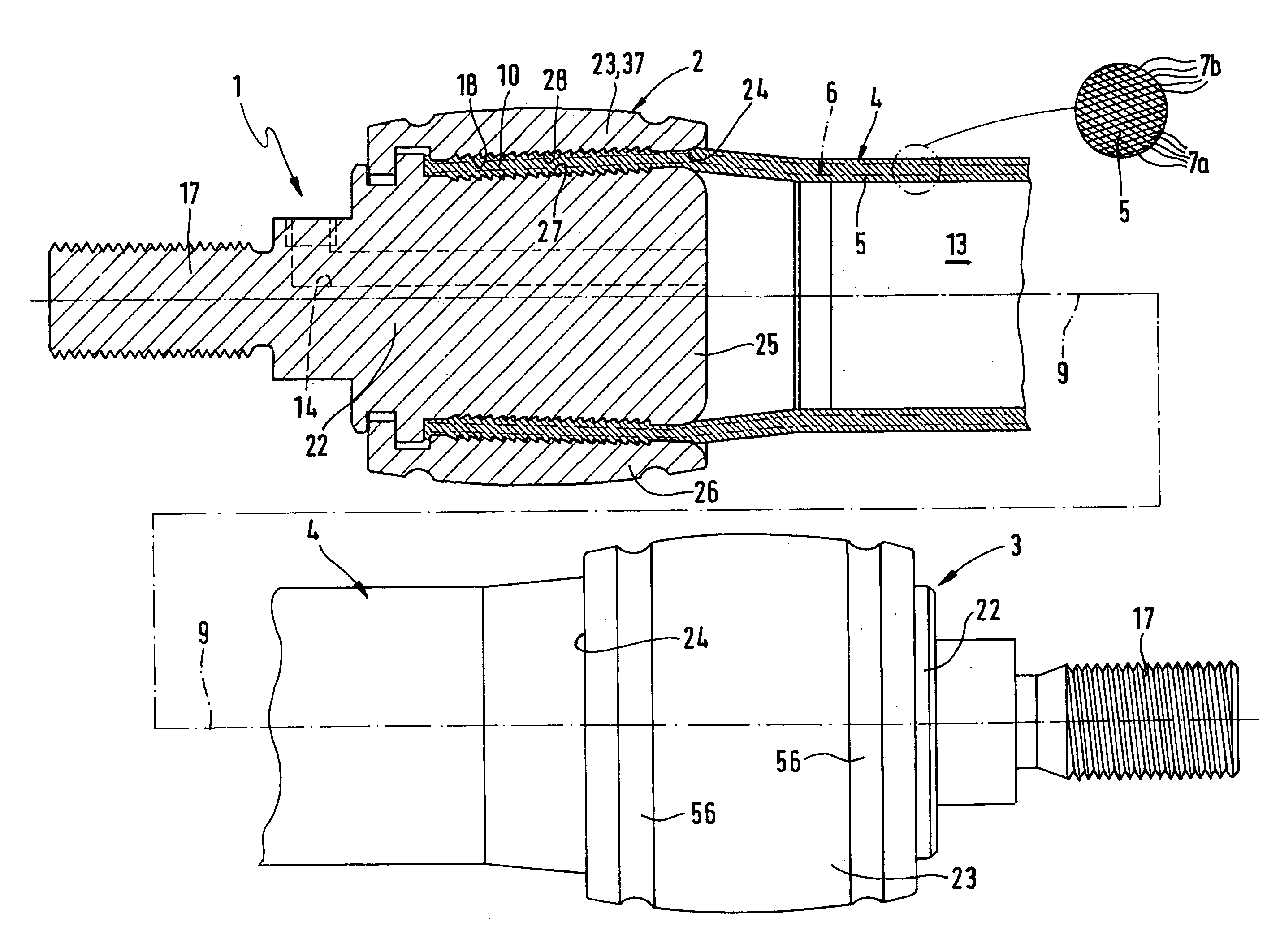
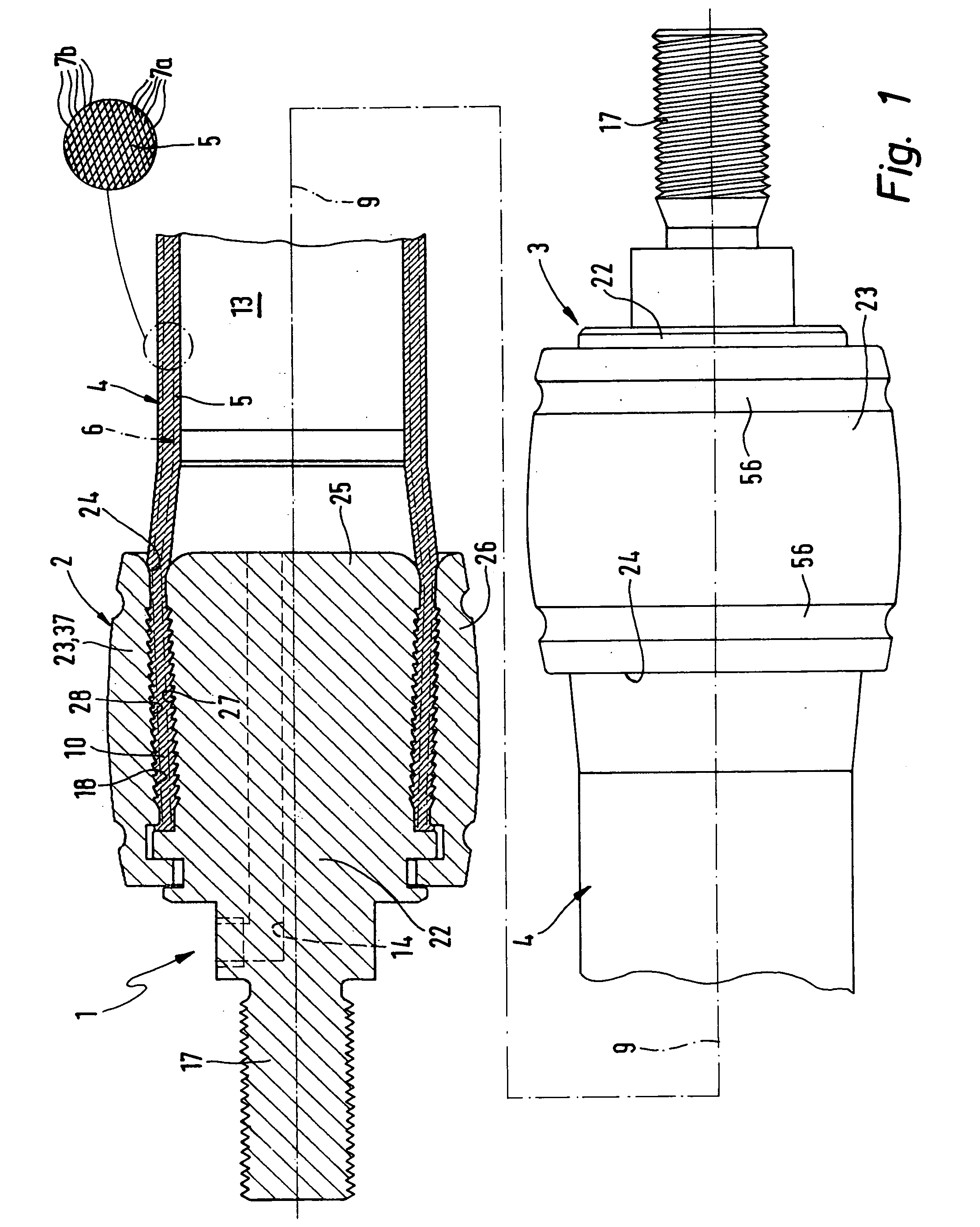
[0022] The actuating means 1 illustrated in the drawings by way of example comprises two first and second head pieces 2 and 3 arranged at an axial distance apart, which are permanently connected together by way of a linearly extending contractile hose 4. At least in the deactivated state of the actuating means 1 the contractile hose 4 preferably has an essentially tubular form.

[0023] As regards details the contractile hose 3 of the working example possesses an elongated hose body 5 consisting of a material with rubber elastic properties. As a material more particularly rubber itself or another elastomeric material is employed. In the wall of the hose body 5 a strand structure 6 is embedded, which is for the sake of simplicity only indicated in chained lines, which is completely surrounded by the material of the hose body 5 and is coaxial to the body.

[0024] Preferably the structural design of the contractile hose 4 is the same as that described in the said patent publication WO 00 / ...


PUM


Abstract

An actuating means adapted for fluid activation has a contractile hose terminally secured by clamping on at least one head piece. The contractile hose fits into an annular clamping gap or nip, whose wall bears saw tooth serrations, the saw tooth serrated areas being so arranged that their teeth are radially opposite each other and arranged in pairs each at the same level. The outer saw tooth serrated area is located on a compression sleeve, which is radially pressed to join it with the hose end section surrounded by it.

Description

BACKGROUND OF THE INVENTION. [0001] The invention relates to an actuating means able to be activated by fluid action comprising a contractile hose, extending between two head pieces and adapted, under fluid action in the space within it, to undergo radial expansion while simultaneously exerting axial tension forces on the head pieces involving a tendency to draw same together, the contractile hose having a hose body of a material with rubber elastic properties and a strand structure embedded in the wall of the hose body with a coaxial arrangement, said contractile hose being secured to at least one head piece by having an end section thereof clamped in an annular clamping gap, which is defined by the outer periphery of an inner head piece part extending axially into the contractile hose and the inner periphery of an outer head piece part coaxially surrounding the contractile hose at the level of the inner head piece part. THE PRIOR ART. [0002] In the case of an actuating means of th...

Claims


Application Information

Patent Timeline
Patent Type & Authority Applications(United States)
IPC IPC(8): F04B43/08F04B43/12F15B15/10F15B15/14
CPCF15B15/103
Inventor SCHANTZE, ACHIMMULLER, ALEXANDERLORENZ, BERND
Owner FESTO AG & CO KG
Learn More