Power drill attachment and method for using the attachment

a technology of power drill and attachment, which is applied in the direction of transportation and packaging, manufacturing tools, portable drilling machines, etc., can solve the problems of difficult to hold precise positions of manufacturable power drills, reach the limits of workers' capacities, and difficulty in using such tools without any aid, so as to reduce the exertion, reduce the danger of injury of power tools, and facilitate use

Inactive Publication Date: 2004-09-09
AIRBUS OPERATIONS GMBH
View PDF29 Cites 20 Cited by
  • Summary
  • Abstract
  • Description
  • Claims
  • Application Information

AI Technical Summary

Benefits of technology

[0006] to provide an attachment for a power tool, particularly a power drill, which will reduce an assembly worker's burden by reducing the force required for performing such drilling work;
[0016] By releasably securing the attachment and thus the power drill to a support, the force to be exerted by the assembly worker, is substantially reduced or even minimized. Thus, the power drill can be more easily used in inconvenient working positions. Further, the attachment carries a leveraged feed advance mechanism which requires little force on the part of the worker for applying a steady, uniform, sufficient and precise feed advance motion to the power drill, and thus to the drill bit. The combination of these features greatly reduces the exertions that an assembly worker had to make heretofore, particularly with the shoulder and arm area. Further, any danger of injury by the power tool is minimized by the present attachment. Thus, the present attachment makes the assembly worker's job more easy and hence more ergonomical. Economically, the benefits are greatly multiplied if one takes into consideration that in the assembly process of a large volume structural component such as an aircraft fuselage, a multitude of precisely drilled holes have to be produced.

Problems solved by technology

Manually operated power tools such as power drills are hard to hold in a precise position while simultaneously assuring a proper feed advance during the drilling, for example in the assembly of an aircraft body or other large scale components.
The difficulties in precisely holding a power drill are aggravated when the different drilling positions are hard to access and / or when the tools or power tools are rather heavy, whereby operating such tools without any aids becomes rather fatiguing.
Thus, this type of work requires substantial strength on the part of the worker and frequently limits of a worker's capacities are reached, which is ergonomically not desirable.
Another disadvantage in connection with freely handheld power drills is seen in that it is very difficult to constantly hold the tool or drill bit in a precisely axially aligned position relative to the hole to be drilled perpendicularly to the surface of the workpiece such as a panel.
These requirements are problematic, particularly where the drilling location is hard to access.

Method used


Image

  • Power drill attachment and method for using the attachment
  • Power drill attachment and method for using the attachment
  • Power drill attachment and method for using the attachment

Examples


first embodiment

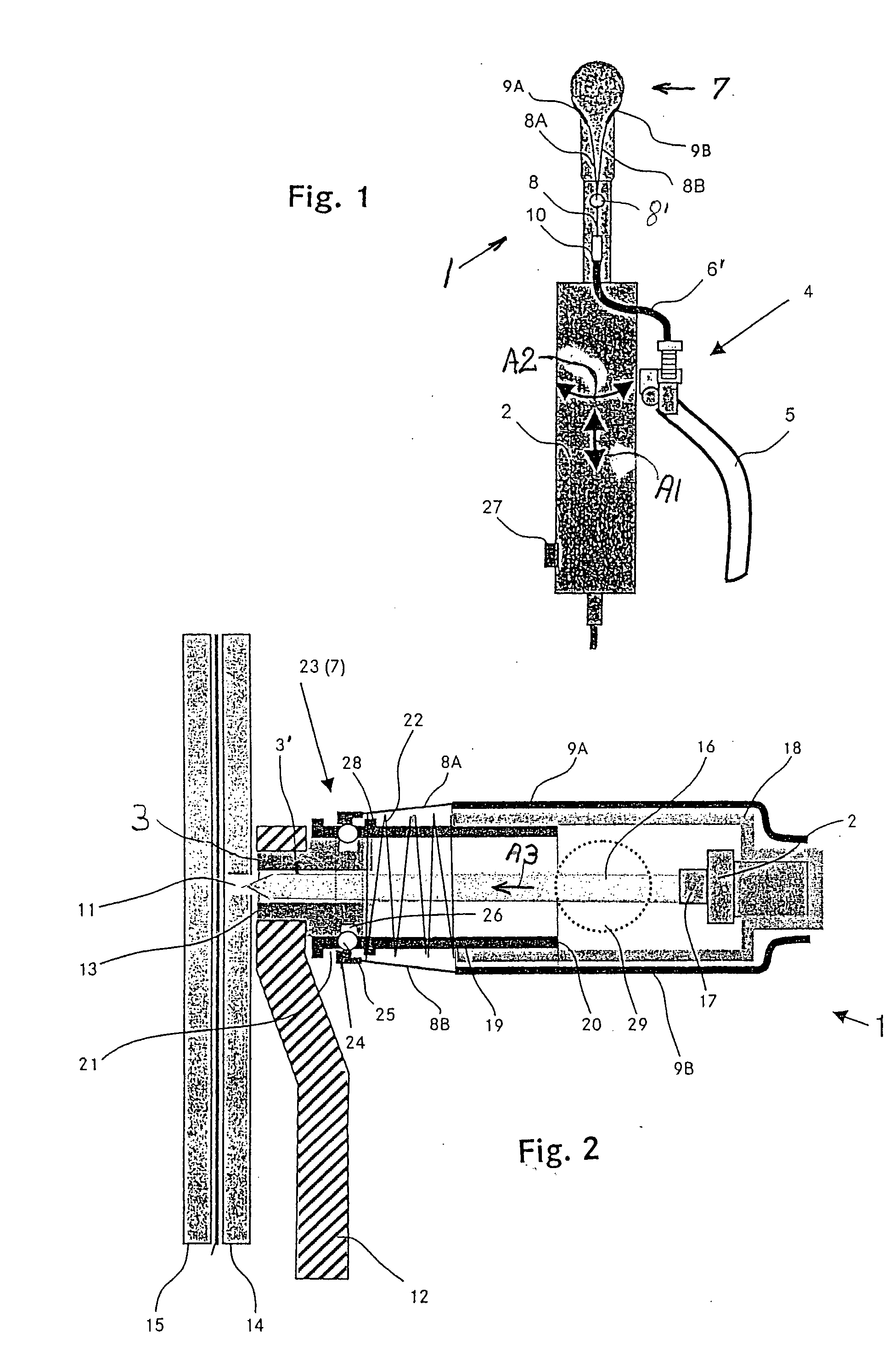
[0026] FIG. 2 shows a sectional view of the attachment 1. The above mentioned drill bit guide bushing 3 is permanently or releasably secured in the bore 13 of the clamping leg 12 forming a support. The bushing 3 forms a guide channel 3' for the drill bit 16. The guide bushing 3 is preferably inserted into the bore 13 of the clamping leg 12 with a location fit or a form fit to thereby assure a precise positioning and axial alignment of the drill bit 16 with the predrilled hole 11.

[0027] This type of positioning is one of several possibilities for using the attachment 1 according to the invention. Instead of the predrilled workpiece 14 a drilling template could be used or the clamping device with the clamping leg 12 could be replaced by a clamping template or by drill clamping tongues.

[0028] The guide bushing 3 has a flange 3" projecting out of the bore 13 of the clamping leg 12 for docking with the latch bushing 19 that is telescoping relative to the attachment bushing 18 which is se...

third embodiment

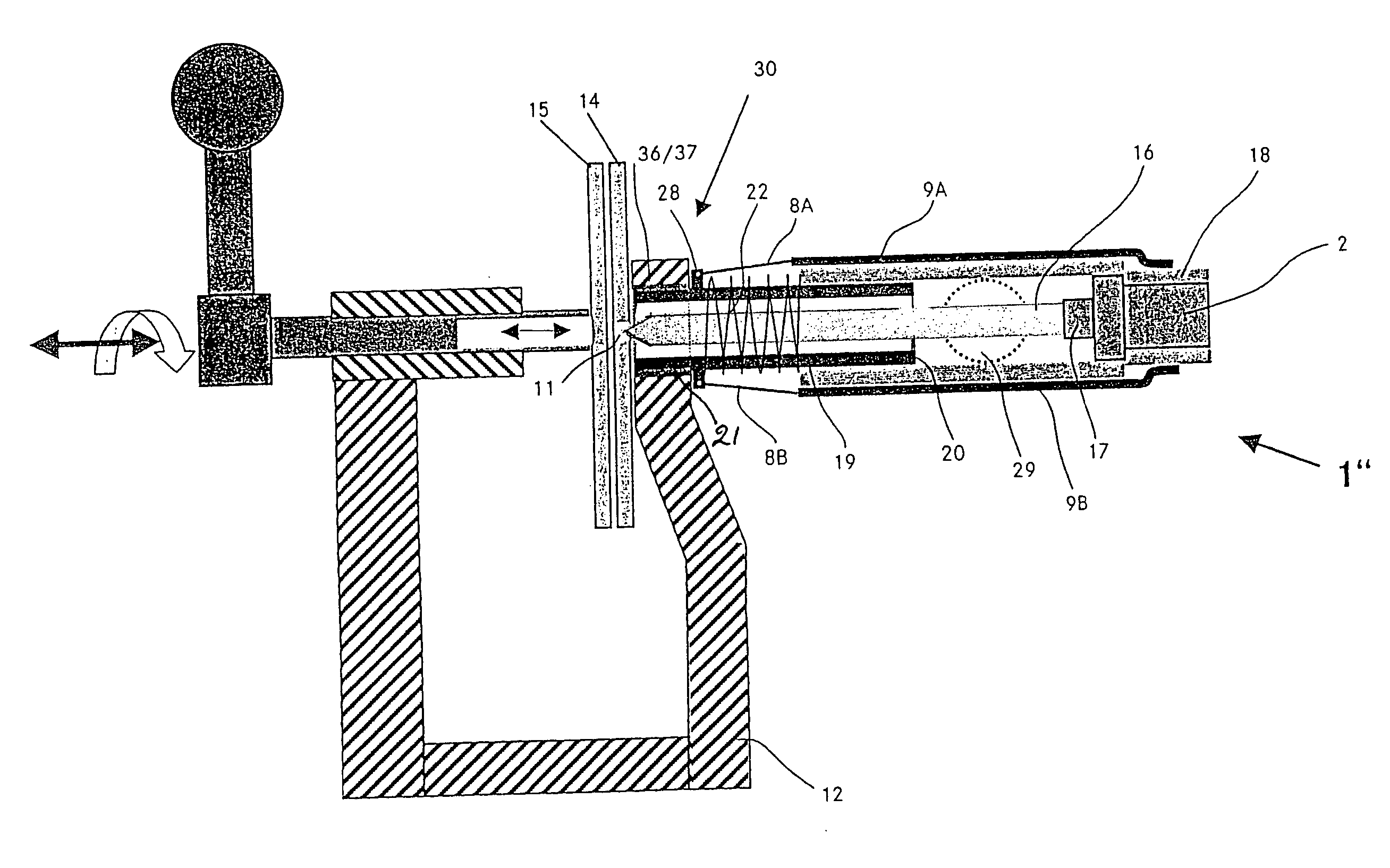
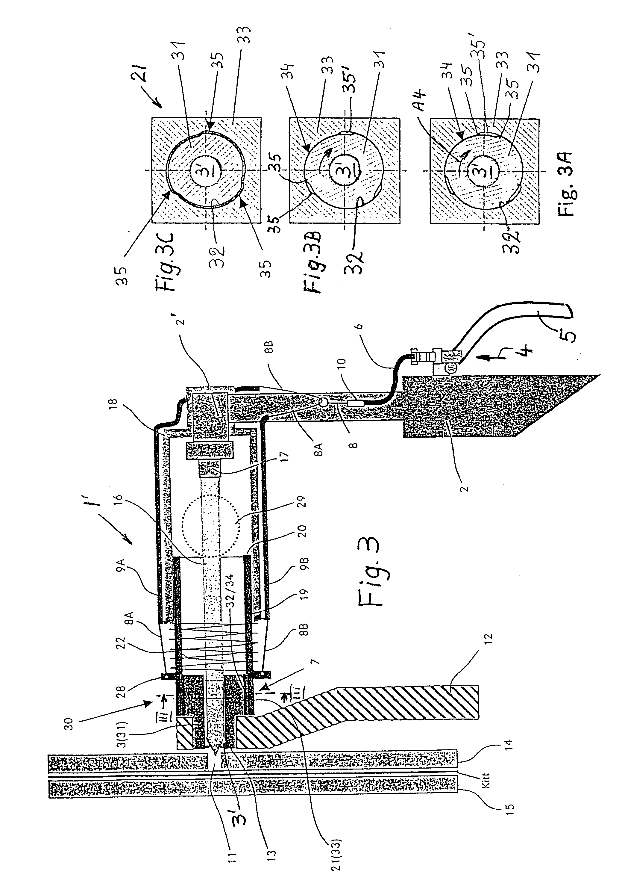
[0035] FIG. 4 shows the drill attachment 1". The interlocking between the front end 21 of the latch bushing 19 and the support 12 is accomplished by a wedging chuck 36, 37 as described above with reference to FIGS. 3A, 3B and 3C. Such a circular wedge chuck assures a connection between the drill 2 and the support 12 without any play and in precise axial alignment relative to the workpiece or rather the hole 11 in the workpiece. The latch bushing 19 is directly inserted into a respective bore 13 in the support 12. The outer surface 36 of the front end 21 of the bushing 19 and the inner surface 37 of the bore 13 are provided with the wedging profiles 35 which cooperate as above described. The embodiment of FIG. 4 is particularly suitable for use of the power drill 2 in places with very little space for the drilling operation. The chucking action of the wedging surfaces 36, 37 is the same as described above with reference to FIGS. 3A, 3B and 3C. The power drill 2 is rotated into the lo...


PUM

PropertyMeasurementUnit
frictionaaaaaaaaaa
drilling depthaaaaaaaaaa
strengthaaaaaaaaaa

Abstract

In order to facilitate and make more ergonomic the drilling of a multitude of holes in workpieces, particularly in the assembly of large scale components, such as an aircraft body, the power drill is docked to a support by an attachment which engages and locks onto a guide bushing or bore in the support. The attachment assures that the drill bit is precisely axially aligned with a hole to be drilled. The feed advance is performed by a leveraged action controlled by the operator. The leverage can be provided, for example by a Bowden pull cable. The attachment reduces the exertion to be made by the operator, thereby avoiding ergonomically unsatisfactory work positions.

Description

[0001] This application is related to Docket No.: 4604, entitled Clamping Mechanism, filed Jan. 8, 2004, by the same inventor as the present application.PRIORITY CLAIM[0002] This application is based on and claims the foreign priority under 35 USC .sctn.119 of German Application 103 03 804.3 filed on Jan. 31, 2003, the entire disclosure of which is incorporated herein by reference.[0003] The invention relates to an attachment that is secured to a power drill for positioning the power drill precisely relative to a hole to be drilled and for facilitating the feed advance of a drill bit.BACKGROUND INFORMATION[0004] In the production of certain large scale components each including a plurality of structural elements, a multitude of rivet holes are required for connecting the structural elements by rivets particularly in the production of aircraft components. Manually operated power tools such as power drills are hard to hold in a precise position while simultaneously assuring a proper f...

Claims


Application Information

Patent Timeline
Patent Type & Authority Applications(United States)
IPC IPC(8): B23B45/14B23B49/00B23Q5/34B23Q5/54B23Q9/00B23Q11/00B25H1/00
CPCB23B49/006B23B2215/04B23Q5/34B23Q5/54B23Q9/0014Y10T408/6757B25H1/0064Y10S408/712Y10T408/6786Y10T408/03Y10T408/564B23Q11/0046Y02P70/10
Inventor OTTEN, JUERGEN
Owner AIRBUS OPERATIONS GMBH
Why Eureka
Try Eureka