Structural Door Module

a technology for building modules and doors, applied in the direction of doors, roofs, transportation and packaging, etc., can solve the problems of high assembly cycle required for assembling doors, hardware and safety components, and less protection for vehicle occupants from side-impact collisions than front or rear-end collisions

Active Publication Date: 2008-11-13
INTIER AUTOMATIVE CLOSURES INC
View PDF13 Cites 23 Cited by
  • Summary
  • Abstract
  • Description
  • Claims
  • Application Information

AI Technical Summary

Benefits of technology

[0014]A second embodiment provides a structural door module for a convertible vehicle door body, comprising of a carrier plate with a plurality of door hardware components mounted to the dryside and wetside surfaces of the carrier plate. A pair of glass guide channels are mounted to two rails on the window regulator. An integrally formed mirror flag is provided on one of the two glass guide channels. A latch presenter is mounted to the other of the two glass guide channels. Each of the two rails is provided with an independent adjustment means that allows the rail to be moved closer to or farther away from the carrier plate.

Problems solved by technology

In general, vehicle occupants are less protected against side-impact collisions than front or rear-end collisions due to the relative thinness of the motor vehicle door.
The conventional installation of the hardware and safety components has, however, several drawbacks.
First, a high assembly cycle is required to assemble the door in this fashion since installation of each hardware and safety component is a separate task requiring human effort.
Second, operability of the hardware components cannot be determined until the respective components are installed onto the door.
Thus, time and labor may be wasted installing inoperable or ill-fitted components.
One disadvantage associated with such door modules is that once the door module is installed to the door, the carrier body typically serves little or no purpose since all of the hardware components are eventually securely fastened to the structural door body and the door module itself does little or nothing to strengthen the door body.
Another disadvantage associated with such door modules is that the door modules themselves are very labour intensive and require a large number of parts and steps to assemble before they can be delivered to the OEM.

Method used


Image

  • Structural Door Module
  • Structural Door Module
  • Structural Door Module

Examples


Embodiment Construction

[0032]FIGS. 1-8 show a first embodiment of the invention, and FIGS. 9-13 shows a second embodiment of the invention.

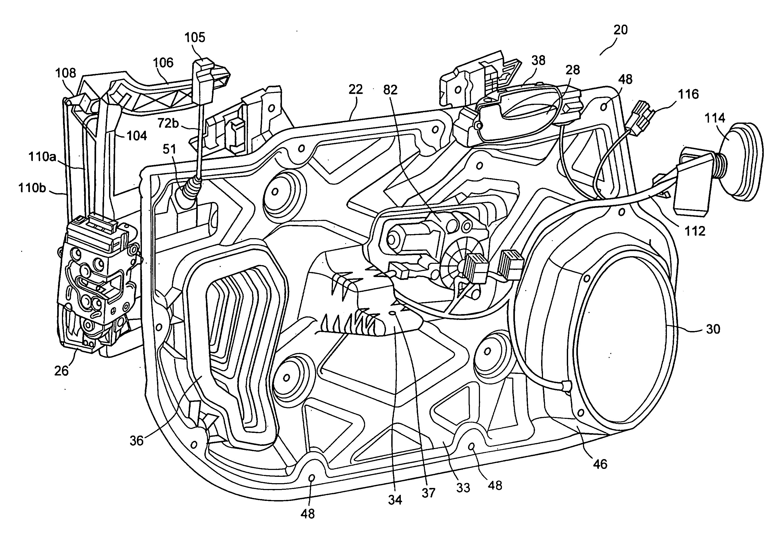
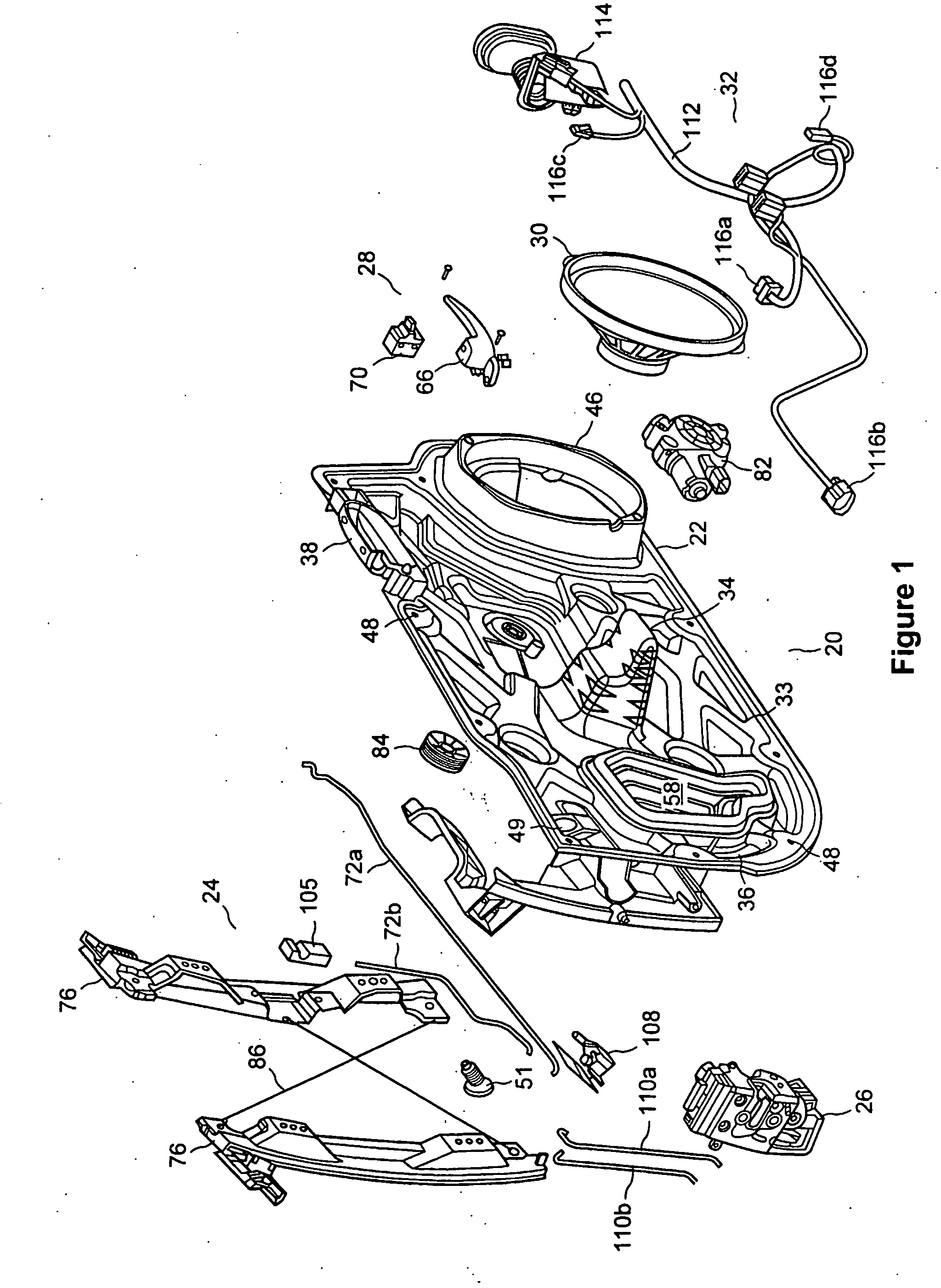
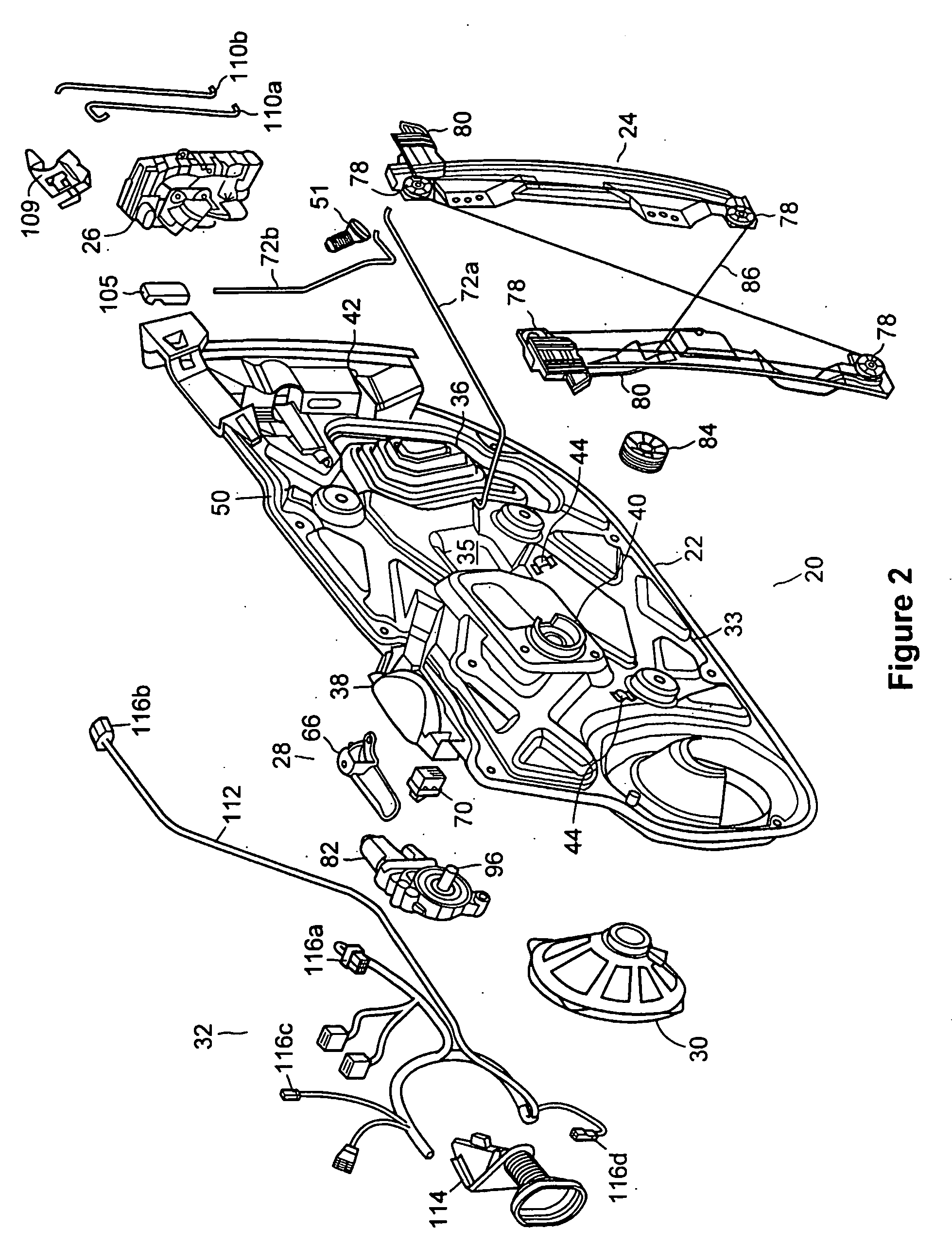
[0033]FIGS. 1 to 4 show a structural door module 20, which includes a plurality of hardware subsystems mounted to or otherwise integrated with a carrier plate 22, and discussed in greater detail below. FIGS. 1 to 2 show an exploded perspective view of the structural door module 20 and FIGS. 3 to 4 are an assembly view of the structural door module 20. Carrier plate 22 provides opposing first and second surface, hereafter referred to as the “dryside” and “wetside” surfaces respectively. Shown in FIG. 1, the dryside surface of carrier plate 22 faces the interior of the vehicle when mounted to a motor vehicle door body (not shown). Conversely, as shown in FIG. 2, the wetside surface of carrier plate 22 faces the exterior of the vehicle when mounted to a motor vehicle door body (not shown). Hardware subsystems that are typically pre-mounted to carrier plate 22 include a wi...


PUM


Abstract

A structural door module for a motor vehicle door, comprising of a carrier plate with a plurality of door hardware components mounted to the dryside and wetside surfaces of the carrier plate. The carrier plate includes a number of preformed components that allow door subsystems to be pre-mounted to the door module and tested prior to mounting the structural door module in the motor vehicle door body. An energy absorbing area is molded into the carrier plate. Additionally, a protruding arm rest support is designed to collapse during a side-impact collision.

Description

FIELD OF THE INVENTION[0001]The present invention relates to a module for a motor vehicle door body. More particularly, the present invention relates to a structural module that both strengthens the motor vehicle door body and acts as a hardware carrier for hardware subsystems in order to minimize subsequent assembly operations.BACKGROUND OF THE INVENTION[0002]A motor vehicle door typically includes an outer sheet metal panel, an inner sheet metal panel, and a plurality of hardware components mounted within an inner cavity formed between the outer and inner sheet metal panels. Common hardware components mounted to a door body include inner and outer door handle assemblies, window regulators, latch assemblies and speaker assemblies, along with their ancillary connecting and electrical components. The complete assembly of the door involves multiple manufacturing steps and numerous parts. Conventionally, an original equipment manufacturer (OEM) will install each individual hardware com...

Claims


Application Information

Patent Timeline
Patent Type & Authority Applications(United States)
IPC IPC(8): B60J5/00E06B3/00
CPCB60J5/0413B60J5/0416
Inventor ROY, PIERRE-XAVIERBROADHEAD, DOUGLAS G.FORTIN, EDMIU, TRAIAN
Owner INTIER AUTOMATIVE CLOSURES INC
Why Eureka
Try Eureka