Radio channel simulation

a radio channel and simulation technology, applied in the field of radio channel simulation, can solve problems such as interference with radio connection, cumbersome tests performed in real conditions, and different duration and strength of signals

Active Publication Date: 2005-12-01
KEYSIGHT TECH SINGAPORE (SALES) PTE LTD
View PDF8 Cites 66 Cited by
  • Summary
  • Abstract
  • Description
  • Claims
  • Application Information

AI Technical Summary

Benefits of technology

[0007] According to another aspect of the invention, there is provided a method of forming a radio channel of a wireless communication system, the method comprising transmitting a signal from a transmitter to a receiver in at least one radio channel of a wireless communication system during a period of time, forming samples of the signal received by the receiver in a digital form, and saving the samples to be used to characterise a temporal and / or spatial behaviour of at least one simulated radio channel in a digital radio channel simulation.

Problems solved by technology

When a radio frequency signal is transmitted from a transmitter to a receiver, the signal propagates in a radio channel along one or more paths having different signal phases and amplitudes, which causes fadings of different duration and strength in the signal.
In addition, noise and interference caused by other transmitters interfere with the radio connection.
Tests performed in real circumstances are cumbersome, since tests carried out outdoors, for example, are subject to uncontrollable phenomena, such as the weather and the time of the year, which change continuously.
In addition, a test carried out in one environment (city A) is not totally valid in a second, corresponding environment (city B).
Thus, the repeatability of a real test is poor and the tests are time consuming increasing costs and the time required to enter the market.
Additionally, testing a mobile device hooked up with large debug equipment is cumbersome, if not impossible.
However, there are problems related to the channel models used in simulators.
The channel models are based on statistical analyses of measured channels, which make the models limited with respect to real channels.
Additionally, only a few channel models have been developed for broadband systems so far and the models tend to be drastically simplified leading to too optimistic results.
Moreover, depending on the environment, the frequency range, the bandwidth and the antenna construction suitable for radio channel models may not be available at all.

Method used


Image

  • Radio channel simulation
  • Radio channel simulation
  • Radio channel simulation

Examples


Embodiment Construction

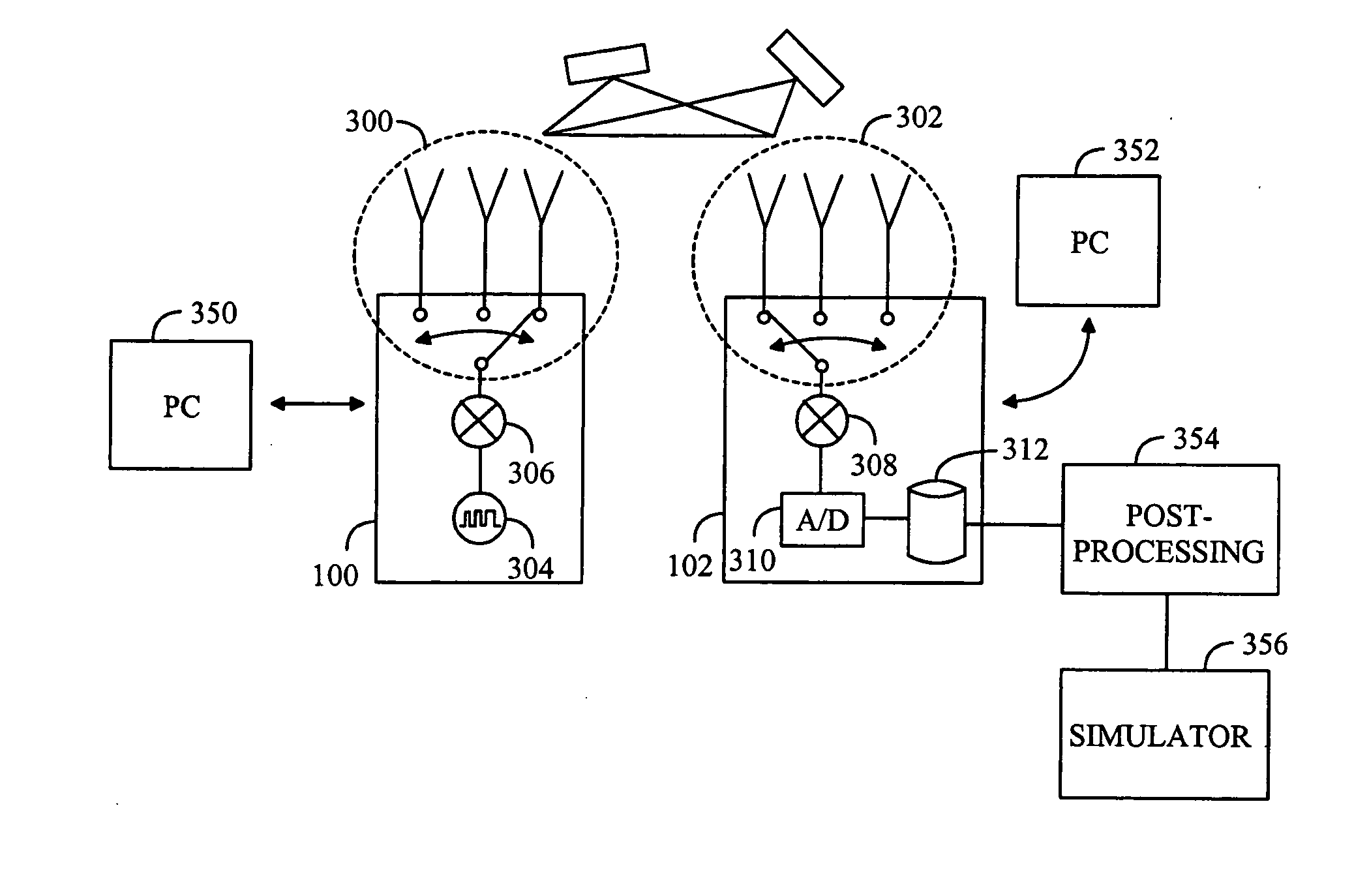
[0028] The present solution is suitable for the channel simulation of a broadband radio frequency signal (RF signal). Examples of the applications include, for instance, WLAN (Wireless Local Area Network), wireless mobile communication systems, and various generations of radio systems, without, however, any restriction thereto.

[0029] In a WLAN system a special transceiver, called an access point, connects equipment of a user to a desired network, which is usually a wired network. The access point is often stationary whereas the equipment of the user can be mobile. One access point can serve a plurality of users within several tens or even hundreds of meters.

[0030] In a radio system, such as GSM (Global System for Mobile Communication), UMTS (Universal Mobile Telephone System), a base station of a network is in contact with one or more user equipment over an air interface. In a similar manner to the access point of the WLAN, the base station has usually a fixed location whereas the...


PUM


Abstract

At least one radio channel is measured and stored. At least one simulation is performed with the at least one radio channel stored.

Description

FIELD [0001] The invention relates to a radio channel simulation. BACKGROUND [0002] When a radio frequency signal is transmitted from a transmitter to a receiver, the signal propagates in a radio channel along one or more paths having different signal phases and amplitudes, which causes fadings of different duration and strength in the signal. In addition, noise and interference caused by other transmitters interfere with the radio connection. [0003] A radio channel can be tested either in real circumstances or by using a radio channel simulator simulating real circumstances. Tests performed in real circumstances are cumbersome, since tests carried out outdoors, for example, are subject to uncontrollable phenomena, such as the weather and the time of the year, which change continuously. In addition, a test carried out in one environment (city A) is not totally valid in a second, corresponding environment (city B). Thus, the repeatability of a real test is poor and the tests are time...

Claims


Application Information

Patent Timeline
Patent Type & Authority Applications(United States)
IPC IPC(8): G06F15/00H04B17/00H04L12/28H04L12/56
CPCH04W24/00H04B17/3912H04W24/06
Inventor KOLU, JANNEKYOSTI, PEKKAJOURDAN, PATRICK
Owner KEYSIGHT TECH SINGAPORE (SALES) PTE LTD
Why Eureka
Try Eureka