Accessory identifier in an electronic device

a technology of accessory identifier and electronic device, which is applied in the direction of measuring device, power supply for data processing, instruments, etc., can solve the problems of increasing the overall cost of the electronic device in terms of the number of parts required for the implementation or as an integration cost for the required parts, reducing the range of identification resistors, and reducing the service life of the electronic devi

Inactive Publication Date: 2005-12-01
MOTOROLA INC
View PDF7 Cites 132 Cited by
  • Summary
  • Abstract
  • Description
  • Claims
  • Application Information

AI Technical Summary

Problems solved by technology

However, the use of a regulated voltage and precision resistors adds overall cost to the electronic device in terms of number of parts required for the implementation or as an integration cost for the required parts.
However, because the CEA-936 interface is designed to be compatible with the existing Universal Serial Bus (“USB”) interface, the range of identification resistors becomes very limited, typically in excess of 100 kΩ, which necessitates tighter tolerance and higher precision methods for detecting and identifying accessories.
Further, because the electronic device is required to detect presence of an accessory at all times through the ID pin, the design using different resistance values to ground for detection and identification of accessories carries the burden of higher current drain due to the fact that the regulated supply must be on at all times.

Method used


Image

  • Accessory identifier in an electronic device
  • Accessory identifier in an electronic device
  • Accessory identifier in an electronic device

Examples


Embodiment Construction

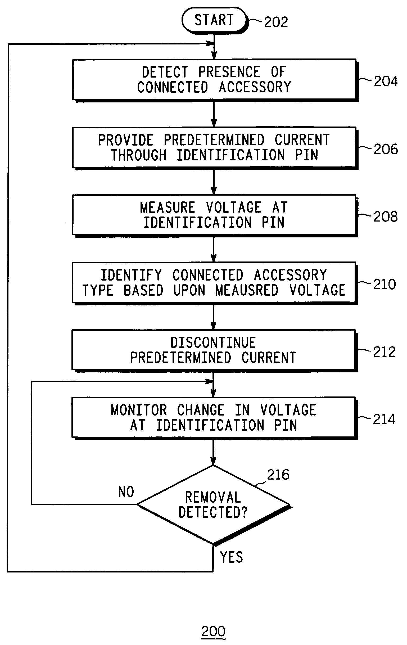
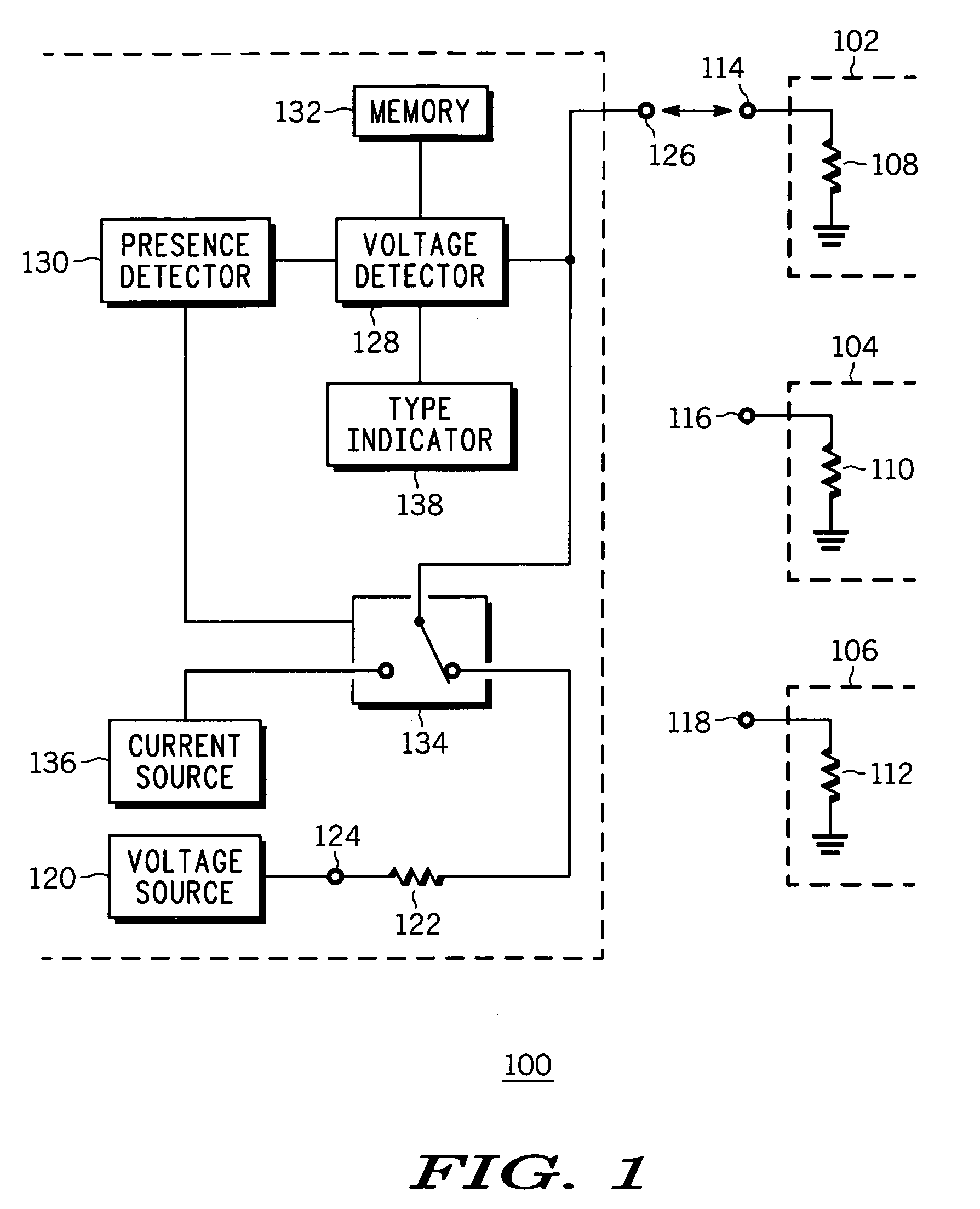
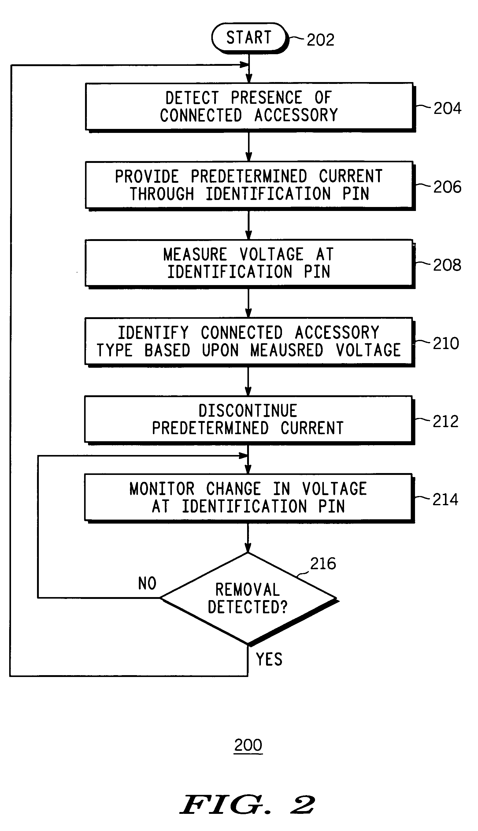
[0006] The accessory identifier provides an apparatus and a method in an electronic device for detecting and identifying an attached accessory from various attachable accessories. Each of the attachable accessories has a unique resister, or an identification resister, connected between an identification pin of the attachable accessory and ground. In a detection mode, the electronic device applies a predetermined voltage provided by a voltage source at a source end of a pullup resister, which is designed to connect to the identification pin of an attachable accessory at a receiving end upon attachment. A change in voltage at the receiving end is monitored to detect presence of the attachable accessory. If there was no attachment, the voltage at the receiving end would be the full predetermined voltage of the voltage source because it is an open circuit. However, if there was an accessory attached, then the pullup resister and the identification resister of the attached accessory woul...


PUM


Abstract

An apparatus (100) and a method (200) for an accessory identifier for identifying a connected accessory type from three or more accessory types (102, 104, 106) are provided. Each of the three or more accessory types (102, 104, 106) has a unique identifier resistor (108, 110, 112), which is accessible through an identification pin (114, 116, 118) and is linearly related to each other in resistance value. Using a voltage source (120), presence of the connected accessory (102) is detected (204) by monitoring a voltage change at the source pin (126). Once the presence is detected, a predetermined current is sent through the source pin (126) and the resulting voltage at the source pin (126) is measured (208), and based upon the measured voltage, the connected accessory type (102) is identified (210).

Description

FIELD OF THE INVENTION [0001] The present invention generally relates to a data bus connection, and more specifically to detection and identification of an accessory attachment through the data bus connection. BACKGROUND OF THE INVENTION [0002] Portable electronic devices, such as personal digital assistants (“PDAs”), personal computers (“PCs”) and cellular telephones, are generally capable of accepting external accessories such as, but not limited to, a camera, a speaker phone, and a battery charger. An electronic device, which supports the “Mini USB Analog Carkit Interface Specification” (“CEA-936”) published by Consumer Electronics Association, Dec. 1, 2002, is required to detect presence of an accessory at all times through an identification (“ID”) pin of a connector that accepts the accessory. In addition, the ID pin is also used to identify the type of the accessory attached to the electronic device. Presently, the identification of accessory types is implemented by using a re...

Claims


Application Information

Patent Timeline
Patent Type & Authority Applications(United States)
IPC IPC(8): G06F1/26G06F13/00G06F13/40
CPCG06F13/4081
Inventor CARLSON, MARK J.
Owner MOTOROLA INC
Why Eureka
Try Eureka