Cover for dispensing closure with pressure actuated valve

a technology of valve head and valve cover, which is applied in the field of containers and closures, can solve problems such as restricting the movement of the valve head

Inactive Publication Date: 2005-12-08
OBRIST CLOSURES SWITZERLAND GMBH
View PDF30 Cites 7 Cited by
  • Summary
  • Abstract
  • Description
  • Claims
  • Application Information

AI Technical Summary

Benefits of technology

[0006] A closure for dispensing a product from a container includes a cover for a flexible dispensing valve. The cover, which is removably coupled to a base of the closure, includes a central post that extends downwardly from a top portion of the cover. A distal portion of the post contacts the flaps of the dispensing valve to inhibit the flaps from opening. The dispensing valve flaps are part of a valve head that open in response to internal positive pressure within the container from their at-rest, closed position. Thus, the post of the cover preferably contacts the flaps at the point of intersection of the slits forming the flaps. Further, an outer circular projection extending downwardly from the top portion may also restrict movement of the valve head. The projection preferably is a ring. The cover prevents inadvertent opening of the valve.

Problems solved by technology

Further, an outer circular projection extending downwardly from the top portion may also restrict movement of the valve head.

Method used


Image

  • Cover for dispensing closure with pressure actuated valve
  • Cover for dispensing closure with pressure actuated valve
  • Cover for dispensing closure with pressure actuated valve

Examples


Embodiment Construction

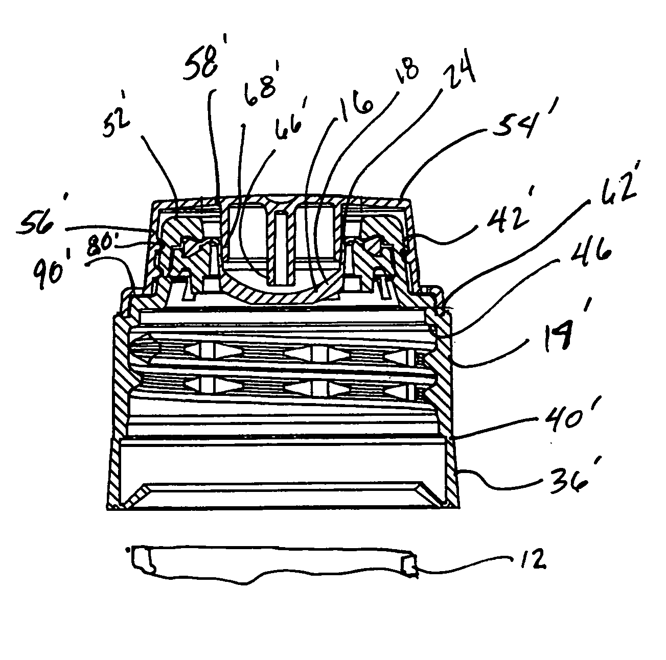
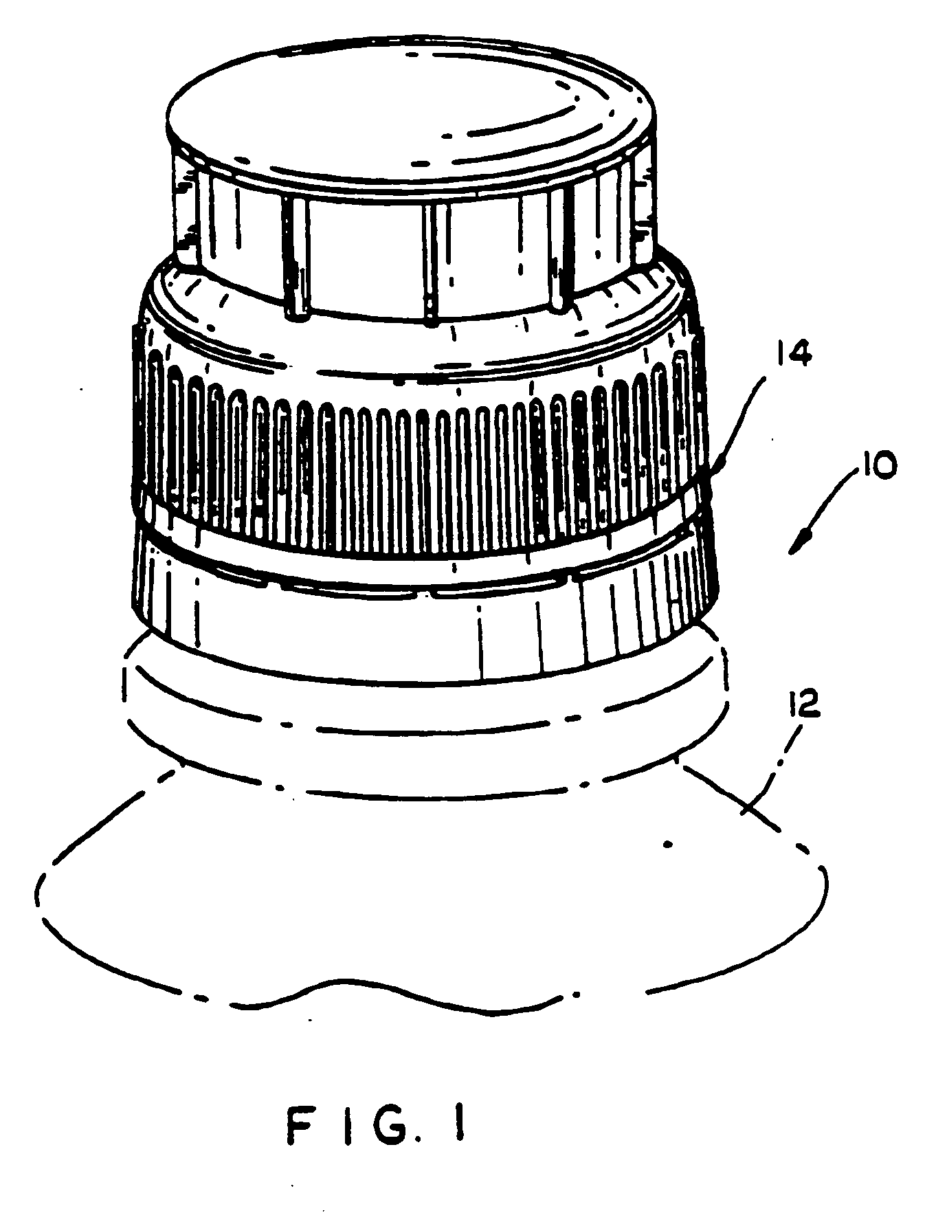
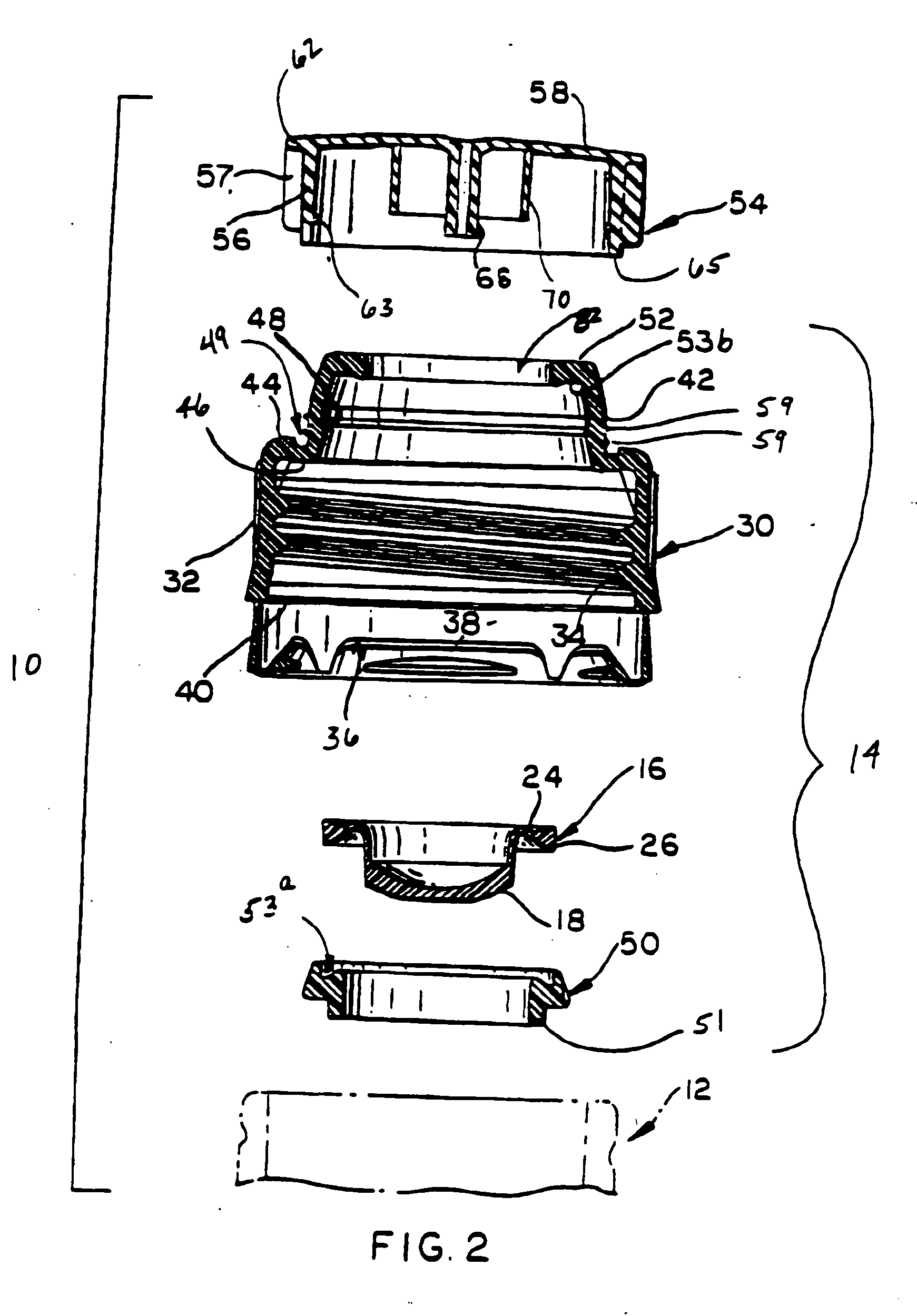
[0021] As shown in FIGS. 7 and 8, a conventional dispensing package includes a container 12 (shown schematically in FIGS. 7 and 8), a valved dispensing closure 14, and a cover 101, each of which is more fully described in U.S. Pat. No. 6089418, which is assigned to the present assignee. The valved dispensing closure 14 includes a self-sealing dispensing valve 16, a base 30, and a retaining ring 50, as shown in FIGS. 7 and 8, and in the lower portion of FIG. 2. Valve 16 comprises a one-piece, integrally-molded member preferably constructed from liquid silicone rubber, or the like. Valve 16 includes a concave valve head 18 with cross-slits 20 defining pie shaped flaps 22 and a discharge orifice therein. Cross-slits 20 and flaps 22 are best shown in FIG. 6.

[0022] A connector sleeve 24 has one end connected with the marginal circumferentially extending flange 26, which is substantially triangular in cross section, and the opposite end connected with valve head 18 adjacent to this margi...


PUM


Abstract

A cover for a valved dispensing closure prevents the valve from opening while the cover is disposed on closure. The cover's central projection prevents flaps formed in the valve from opening, and the cover's outer projection prevents the flexible valve head from moving or inverting. The cover may also have projections that project inwardly from its skirt. The cover projections interact with mating projections formed on an exterior of the closure, and a lower end of the skirt may be disposed into an annular groove in the closure, to enhance a seal between the closure and the cover. The cover may include a snap ring attached to other portions of the cover by a breakable connection to provide tamper evidence.

Description

[0001] This application is a continuation-in-part of prior application Ser. No. 10 / 098,819, which was filed on Mar. 15, 2002 and is incorporated herein by reference in its entirety.FIELD OF THE INVENTION [0002] This invention relates to closures for containers, and more specifically to dispensing closures having pressure activated valves and corresponding covers. BACKGROUND OF THE INVENTION [0003] A flexible dispensing valve system may be part of a package that is suitable for storing, shipping, and dispensing both high and low viscosity materials. Such high viscosity materials include shampoos, conditioners, soaps, and other flowable products such as other liquids, pastes and the like. Low viscosity materials include water, other beverages, and the like. The dispensing system, upon being inverted and / or squeezed, opens a self-sealing dispensing valve in the closure at a predetermined threshold pressure to discharge the contents of the corresponding container. Upon removal of the ex...

Claims


Application Information

Patent Timeline
Patent Type & Authority Applications(United States)
IPC IPC(8): B65D47/20
CPCB65D47/2031
Inventor GAISER, RICKY G.HIERZER, VALENTIN
Owner OBRIST CLOSURES SWITZERLAND GMBH
Why Eureka
Try Eureka