
Stackable bins and storage media rack therefor

a technology for stackable bins and storage media racks, which is applied in the field of stackable cases or bins, can solve the problems of stackable bins, the front end of the side walls of the bins moving outwards, and the instability of the top bin

Inactive Publication Date: 2005-12-08
OHAYON ABRAHAM
View PDF35 Cites 6 Cited by
  • Summary
  • Abstract
  • Description
  • Claims
  • Application Information

AI Technical Summary

Benefits of technology

[0007] It is therefore an object of the present invention to provide a stackable bin that enables variations in the size of object-containing receptacles defined by the bin.
[0010] It is another object of the present invention to provide a stackable bin that provides a reliable interlocking arrangement of the bins in a stacked configuration thereof In order to achieve one or more of these objects and other objects, one embodiment of a stackable bin in accordance with the invention comprises a case including a bottom wall, a top wall and a support mechanism for supporting the top wall at a distance from the bottom wall to thereby define a slot. A drawer is insertable into the slot and defines a receptacle capable of receiving objects for storage. A partitioning structure is also provided for partitioning the receptacle into smaller compartments.
[0012] To enable stacking of a plurality of the bins on top of one another, a peripheral rib is formed on a bottom surface of the bottom wall of the case and a peripheral rib formed on an upper surface of the top wall of the case and offset from the peripheral rib on the bottom wall. These peripheral ribs serve to align the bins in a vertical configuration to form a stable stack of bins.

Problems solved by technology

A problem occurs, however, if the bins have a small dimension without the central partition wall.
Specifically, inner pressure from the goods in a stacked bin may cause the front ends of the side walls of the bin to move outwardly.
This, in turn, can cause instability in the top bin, since the bottom of the top bin stacked thereon could fall down within the side walls of the lower bin.
The stackable bins in the '037 patent and the '388 patent generally do not enable easy variations in the size of the object-containing receptacle.

Method used


Image

  • Stackable bins and storage media rack therefor
  • Stackable bins and storage media rack therefor
  • Stackable bins and storage media rack therefor

Examples


Embodiment Construction

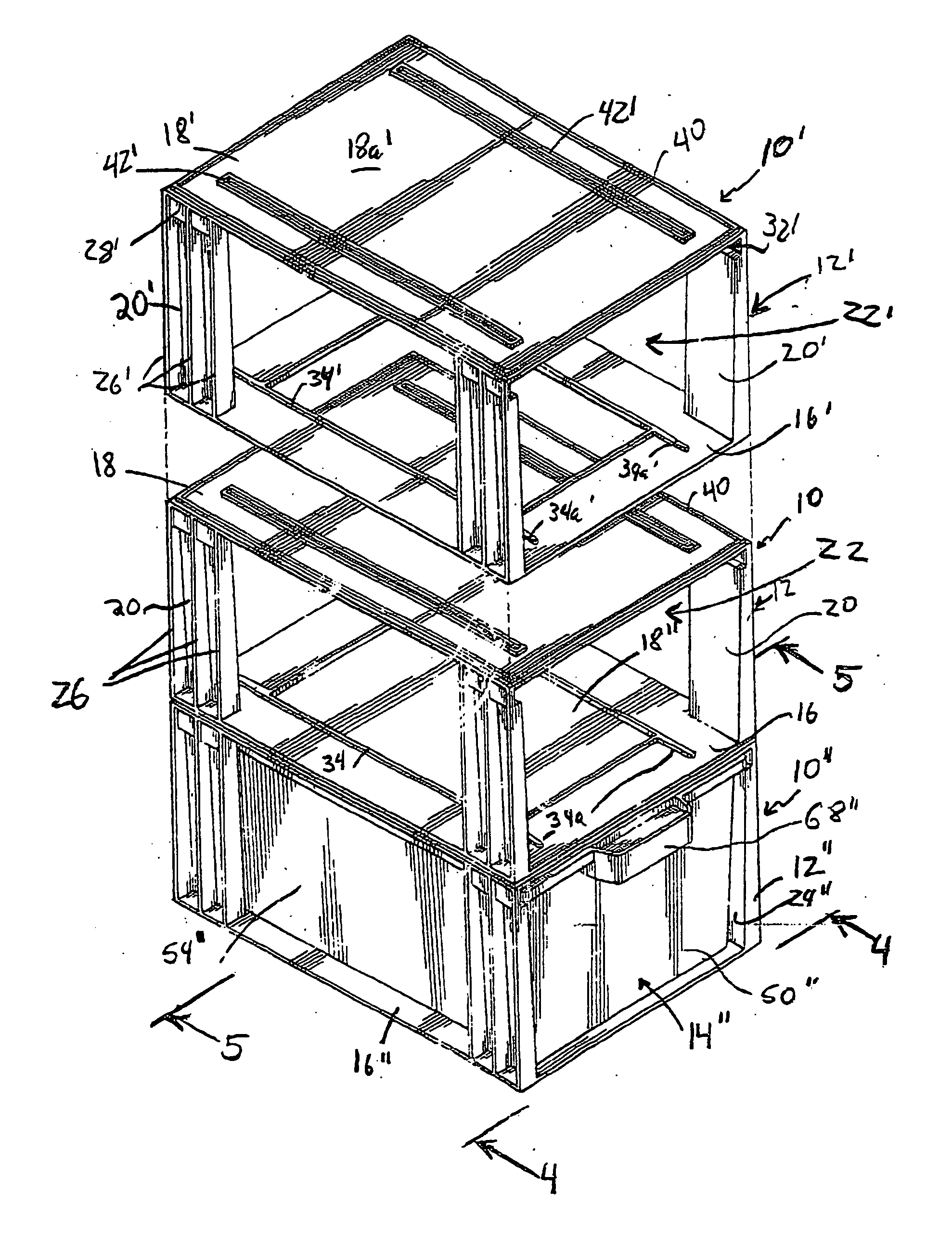
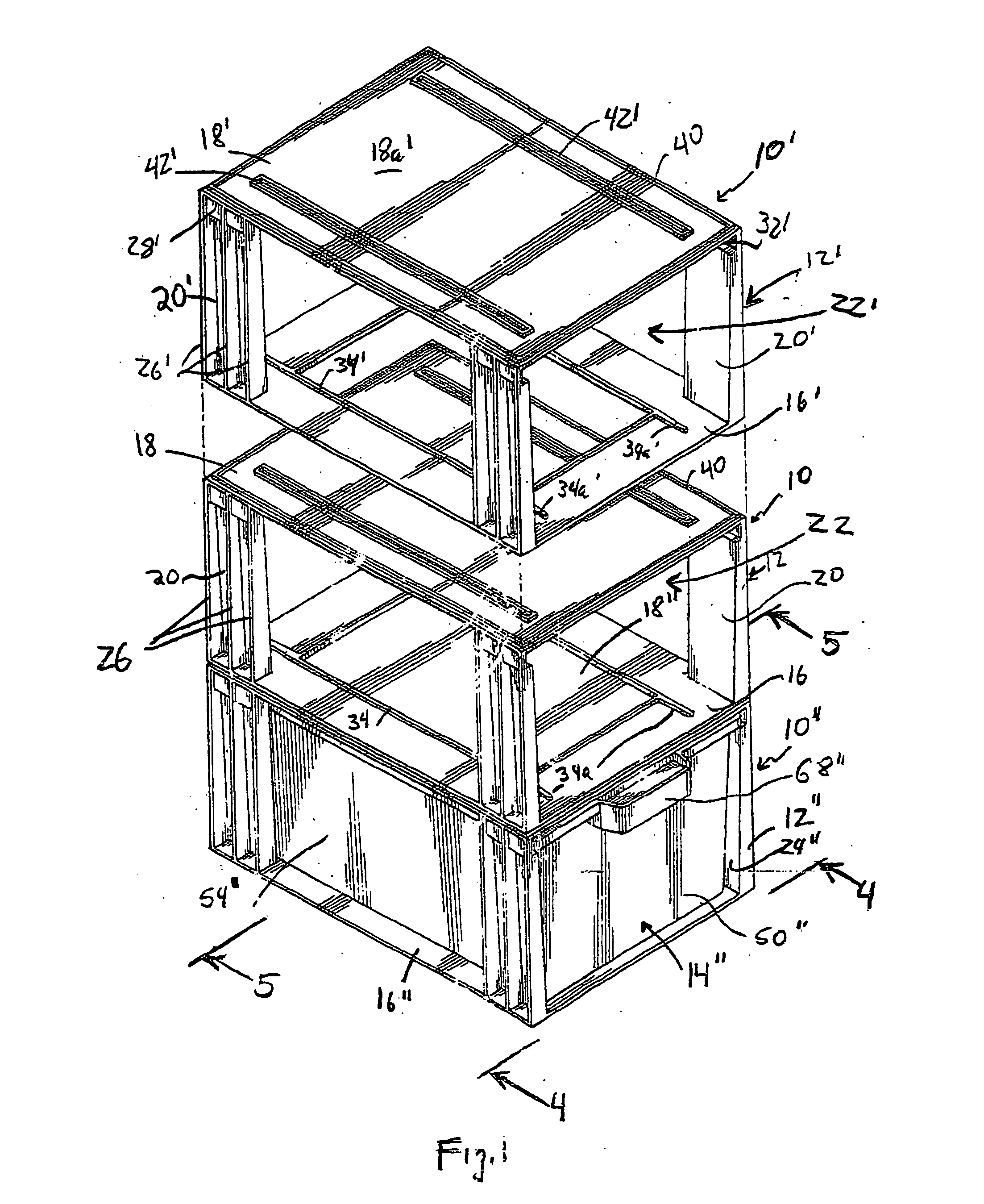
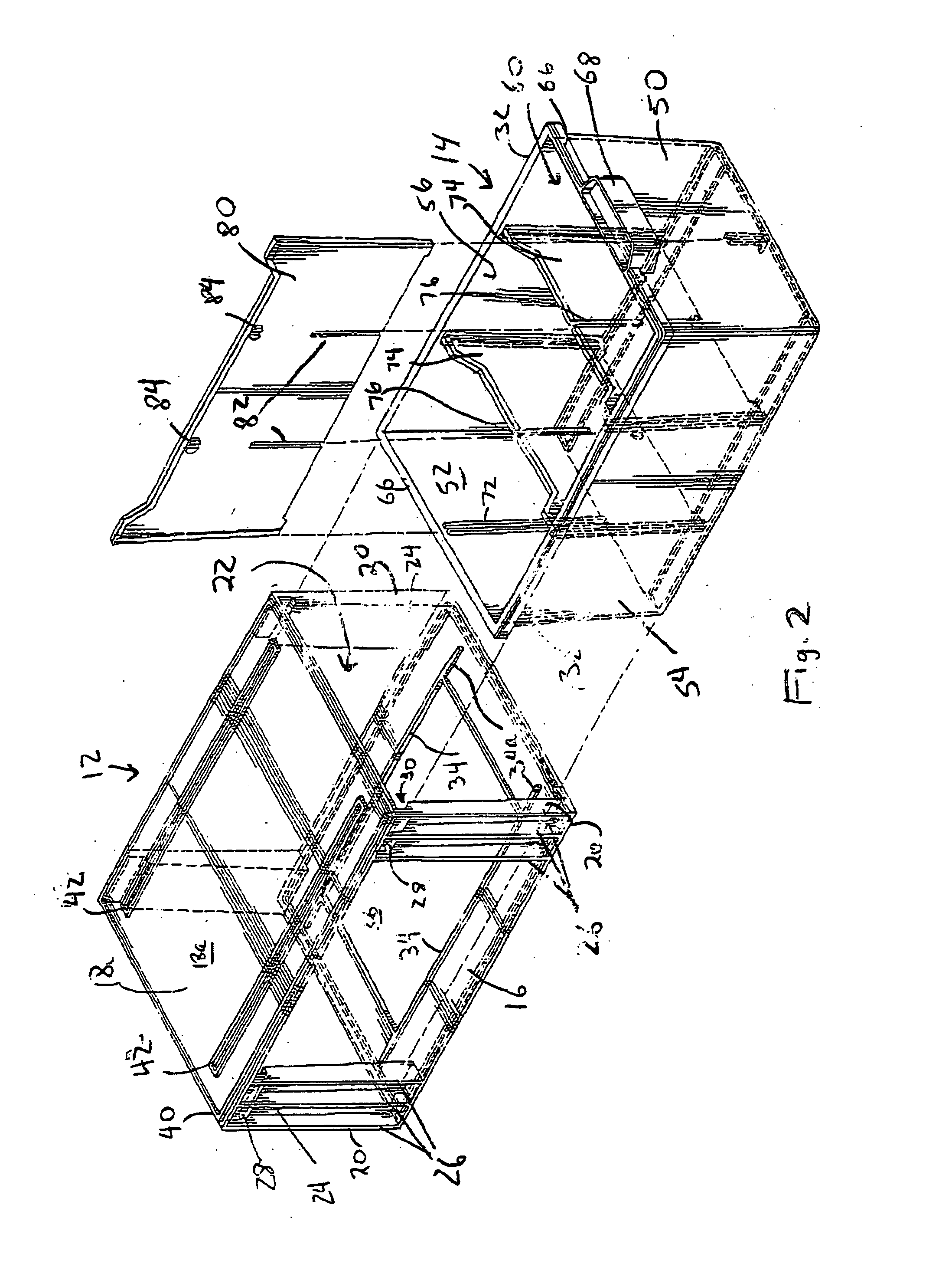
[0029] Referring to the accompanying drawings wherein like reference numerals refer to the same or similar elements, FIGS. 1-8 show a stackable bin 10 according to the present invention. The bin 10 is formed as a multi-piece construction in which the basic bin 10 includes a case 12 and a drawer 14. Since the present invention will be described with reference to bins that are stackable, the notation to be used hereinafter refers to a prime (′) after a numeral to represent the top one of a group of three stacked bins 10, a double prime (″) after a numeral to represent the bottom one of the three stacked bins and a numeral by itself to represent the center bin of the three stacked bins and to describe the parts of a single bin in general. Also, the longitudinal direction of the bins 10 will be considered a direction perpendicular to the front and rear faces of the bins 10 (parallel to the lateral or side faces of the bin 10) whereas the lateral direction will be considered a direction ...


PUM


Abstract

Stackable bin including a case having a bottom wall, a top wall and a support mechanism for supporting the top wall at a distance from the bottom wall to thereby define a slot. A drawer is insertable into the slot and defines a receptacle capable of receiving objects for storage. A partitioning structure is also provided for selectively partitioning the receptacle into smaller compartments with several different configurations of the smaller compartments being possible. Instead of the partitioning structure, a storage media rack may be inserted into the receptacle in the drawer and is arranged to simultaneously receive different sizes and types of storage media.

Description

FIELD OF THE INVENTION [0001] The present invention relates generally to stackable cases or bins, and more particularly, to stackable cases or bins dimensioned to hold consumer articles, such as shoes. [0002] The present invention also relates to a storage media rack or tray insertable into a stackable bin and which enables different sizes and types of storage media to be simultaneously accommodated in the bin. BACKGROUND OF THE INVENTION [0003] Stackable bins for holding articles are well known. For example, stackable bins have been proposed by the same inventor herein, and which are the subject matter of U.S. Pat. No. 5,593,037, issued Jan. 14, 1997, and U.S. Pat. No. 6,062,388, issued May 16, 2000, the entire disclosures of which are incorporated herein by reference. [0004] According to the '037 patent, a stackable bin is provided having reinforcing ribs that perform a two-fold function of reinforcing the walls while also supporting the bin in a stacked arrangement, and in which ...

Claims


Application Information

Patent Timeline
Patent Type & Authority Applications(United States)
IPC IPC(8): A47B87/00A47B87/02A47B88/20B65D1/24B65D1/36B65D25/04
CPCA47B88/20A47B87/0207A47B88/975A47B88/90A47B88/994
Inventor OHAYON, ABRAHAM
Owner OHAYON ABRAHAM
Learn More